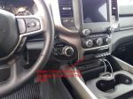
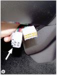
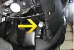
To see if this custom-fit item will work for you please tell us what vehicle you'll use it with.
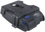
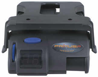
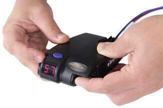
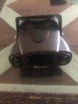
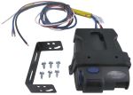
This proportional brake controller has simple controls and a digital display for diagnostic information. Includes 3 boost levels, a slide-bar manual override, built-in battery protection, automatic leveling, and continuous diagnostics.
Features:
Specs:
You can adjust the gain (also known as output) with the thumbwheel on the front of the controller. Gain lets you set the maximum amount of power that will be applied to your trailer's brakes. A heavier trailer will need more power to achieve smooth, safe braking, while a lighter trailer will need less. Typically, the gain is only readjusted when you experience changing road conditions or if the weight of your trailer changes.
The boost setting controls the aggressiveness of your trailer's braking, meaning how quickly the brakes reach the maximum braking level. You can adjust this when you're towing heavy loads and you need more umph to bring your trailer to a stop. Your tow vehicle doesn't need that much power to brake in time, but your heavy trailer does.
Depending on the level of boost, your trailer brakes can start at either 13 percent or 25 percent of the set gain. What this means is that, instead of starting at 0, the brakes will start at 25 percent and get to 100 percent sooner. This keeps the trailer from pushing your tow vehicle forward.
If your trailer weighs less than your tow vehicle, no boost is needed. But, if you want your trailer to lead the braking, you can select level B1.
Boost Levels:
| Approximate Gross Trailer Weight | Boost Level | Increase in Initial Power Output |
|---|---|---|
| Less than tow vehicle GVW | B1 | 13% |
| Equal to tow vehicle GVW | B1 or B2 | 13% or 25% |
| Up to 25% more than tow vehicle GVW | B2 or B3* | 25% |
| Up to 40% more than tow vehicle GVW | B3* | 25% |
*Both B2 and B3 offer a 25-percent boost in initial power. But the braking curve for B3 is more aggressive than that of B2. This means that, even though you will start out with the same intensity when using these boost levels, you will get an overall more aggressive braking experience with the higher level. So if you use B3, you will reach maximum braking sooner than if you use B2.
To adjust the boost, use the blue push-button on the top of the Primus IQ.
The Tekonsha Primus IQ comes with an easy-to-reach, slide-bar manual override, great for stopping sway or controlling your trailer's momentum in emergencies. To engage the manual override, just push the slide-bar to the left, towards the center of the controller. This will activate the trailer's brakes and brake lights without you having to apply the brakes on your tow vehicle, perfect for limiting trailer movement while you're cruising.
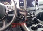
The Primus IQ can mount between -90 degrees and 90 degrees vertically, but the brake controller still needs to be horizontally level and parallel with the direction of travel.
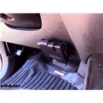
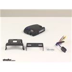
After mounting the Primus IQ unit in your cab using the included bracket, simply plug the included custom harness into your vehicle. The other end of the harness plugs into the brake controller. To remove the IQ for storage when you're not using it, just unplug the unit and slide it out of the bracket. With a replacement wiring harness (sold separately) and replacement bracket (6927 - sold separately), you can even transfer the IQ to another vehicle.
Note: If you don't already have a 7-way plug at the back of your vehicle, take a look at our exclusive 7- and 4-way brake controller installation kit (ETBC7 - sold separately).
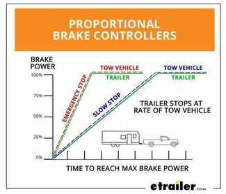
The Tekonsha Primus IQ brake controller comes equipped with proportional braking to give you the best towing experience. Proportional braking means that your trailer brakes mimic your tow vehicle's brakes. If you slam on the brakes in your vehicle, your trailer brakes will activate with the same intensity; if you brake lightly, your trailer brakes lightly too. The trailer's braking is in proportion to your vehicle's braking. This saves wear and tear on the tires and the brakes on both your vehicle and trailer.
The Primus IQ uses an internal inertia sensor to detect how your vehicle is braking so it can send the right amount of braking power to your trailer. It measures the inertia of your tow vehicle and activates the trailer's brakes to slow at the same rate. The result is uniform braking across your towing setup. No push-pull action - just smooth, proportional braking every time.
California residents: click here
Videos are provided as a guide only. Refer to manufacturer installation instructions and specs for complete information.
Today on our 2008 Ford Escape we'll be installing the Tekonsha Primus IQ trailer brake controller, part number TK90160. Now this button on top here is our boost control. This will adjust how much brake power goes to our brakes when we are towing heavier loads. We're going to dial up our boost level settings as appropriate to give us more power. Basically what that means is that the boost settings will give you more intense braking faster than if you had the boost levels turned off. Now, if you want to adjust your braking power, you turn it all the way down off so when I hit our manual lever here, you can see we have no assist. We had it all the way up to 11.
You can dial it down as necessary. What these numbers mean is how many amps are going to your trailer brake so if 11, you have about 11 amps. Now, since our brake controller is adjust to go all the way down from zero and all the way up to 11, a good place to put this will be somewhere right in the middle so you can figure out where you need to go on your brakes. We're going to put ours right about six. That's the standard setting from about most trailers you'll encounter so that should give you adequate stopping power. If you need to have more you can always adjust it there.
One nice feature about this particular brake controller over others is that it has an internal sensor built into it that allows it to be mounted anywhere from 0, which is perfectly flat, up to 90 vertical. Depending on the angle of your dash, you'll be able to mount this and your brakes will be able to function just fine on your trailer. That's a very nice feature about this particular controller over others. Now this is a proportional brake controller. It will activate your trailer brakes in proportion to your vehicles braking action. It automatically adjusts the trailers braking based on the acceleration of your vehicle that youre towing with and it activates immediately.
Theres no pausing like with time delayed brake controllers. There are three boost level settings which allow you to adjust the initial braking power and aggressiveness. You can control it off this button right here. This is your boost control button. Now, the Primus IQ also features a built-in slide bar manual override so if you want to manually apply your trailer brakes in order to help your trailer back in line behind your vehicle, if youre going down a steep hill and it starts to step out to the side, you can do that to slow it down without applying the brakes in your vehicle as well, potentially making the situation worse. This will allow you only to apply the brakes on the trailer and not your vehicle brakes. Another nice feature about this, it does have a built-in safeguard to help prevent overheating to your trailer brakes during prolonged stops.
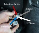
It will reduce the power tune 00:02:54 so you don't have to worry about burning out the magnets in your brakes. This is what our brake controller comes with. We have our Primus IQ brake controller here, our wiring harness, which we'll make our connections with. It's a quick connection here so if we want to remove our brake control and put it in a different vehicle, we can easily do that. We have two different forms of mounting brackets here, more of a holster style, and then one where we have some more adjustment as far as the angle where we can control the angle of how our power brake controller's mounted inside our vehicle so we can easily access the buttons and see the display easier and we have our mounting screws. Now in our particular instance, on our Escape, we have a four wire system already in the back. It was just controlled lighting. There is no existing factory 7 way 00:03:42 on the vehicle. In order to ease our installation we'll be using our kit over here. This is the ETBC7 kit. This provides you with all the accessories you need in order to get a functional 7 way on the back your vehicle. You got your 7 way here and then a 4-pole here. This allows you to hook up a brake controller on any vehicle provided you already have your four flat to tie into. A couple other connections here for . You got your blue wire, which is your break output signal from your brake controller, your black wire which is your 12 volt power source, your white wire is your ground and this purple wire is for your reverse input so if you we're towing a boat trailer, this will lock out the reverse solenoid on your hydraulic brakes so you can safely back up your trailer without the brakes being applied. If you have hydraulic surge brakes, or if you have a trailer that actually has reverse lights on it, this will power those. We have our installation hardware here of several butt connectors, ring terminals, zip ties, and the circuit breakers that we'll need. We have a mounting bracket here to mount our 7-pole to our vehicle. More installation hardware to secure our brackets on our vehicle and our 7-pole to the bracket. Then a roll of duplex wire to run to the back of the vehicle to supply the power and the brake signal from the brake controller. inaudible 00:05:11 wire loom. Now the reason you want a brake controller is if youre going to be towing a heavy trailer that has brakes, you need a brake controller in order to control those brakes, provided they're electric brakes. This brake controller here will allow you to control all electric brakes from 1 to 3 axle trailers. Now we'll start off our installation by finding a place to mount our bracket that our 7 way will attach to. In order to do this on this particular vehicle, I used one of our brackets that we have available on our website. It's part number 18136. It's a long bracket that clamps to your hitch or your frame of your vehicle using an included clamp to give you a mounting surface to attach this to. Do you see It has pre-drilled holes in it that line up with with our bracket that we have here today. Put a little bit of a bend in it here so we can tuck it up nicely, but still have room to install our hardware. You can just stick it in a vice and bend it with a hammer, or your hands. Using the provided hardware that comes with our ETBC7 kit, we'll mount our bracket. We'll slide our bracket over it, like so. We'll use a screw and a washer and come through the outer holes. Hold it in place. Then we'll use our lock washer, star lock washer and nut on the bottom screw. Secure it all. Now we'll use a 5/16 wrench and a screwdriver and we'll tighten these down a little bit. Now we'll take our 7 way and feed all the wires through the large hole. Place it inside and we'll secure it with the included hardware. Push the screw on through and thread the nut into the backside. Do that for all four locations and it's easy to have this cover off so you have a little more room. Now we'll hold the nut in place with a wrench and tighten the screw on down with the screwdriver. Okay, with that done we have a nice solid mount for our 7 way now and our 4 flat. Now we need to connect our 4-pole flat that's already on our vehicle with our new 7 way. We'll just plug it in. One thing I like to do is run a zip tie between our wires like this and we'll secure it by pulling back on the zip tie. This will keep our connection from ever becoming unplugged. We'll cut off our excess zip tie right here. I'm going to off this dust cover that was on our 4 flat because we're not going to need it anymore. I'm also going to wrap our connection up with some electrical tape, which we have available on our website if you need to purchase any, just to help prevent any moisture from potentially entering our connection. Now we'll just stick this up here and zip tie it up out of our way, attach it to the hitch. This will keep it hidden and secure. Now that we have that tucked up out of the way, we can take our purple wire. This is a reverse white wire. We're not going to be utilizing that today, but in case we ever need it again in the future we're just going to secure it up with a zip tie and some electrical tape to help protect the connector so we dont have to worry about that being damaged from corrosion or the elements. Wrap it on up. Now we need to attach our ground wire to the vehicle's chassis. We'll do that with the included self-tapping screw. Let's take our ground wire here, route over the hitch here. We'll find a good place to secure it to the chassis. Right here by this brake line will be a great spot for us. Okay, that gives us a great solid ground point. With our connection grounded now, we can grab an end of our gray duplex wire. We need to separate our wires inside so use a utility knife. Go in between them, pullback. There's two individual wires inside there. Cut off the end right here. I'll strip off the insulation from the wires, that makes two connections on the back of our 7 way. We'll strip off the insulation from both wires and we'll make a connection. For ease of use we'll go black to black and then we'll do the white to blue. Crimp it down with the provided butt connector that's already installed on our 7 way. Okay, with these two crimped down, we'll wrap them in electrical tape just like we did our other connection, just help keep them protected from the elements. All right, now that we have our connections all wrapped up in tape here, we need to start routing the other end of our duplex wire towards the front of vehicle, towards the engine compartment. Now when we do this we need to make sure we pay consideration and in fact, we need to avoid moving parts, such as a suspension and avoid any sources of heat such as the exhaust. I'm going to go ahead and do that now and show you how I did it once and done. We started off by getting our wire here zip tied to the side of our trailer hitch. You may or may not have this option depending on the hitch that you have on your vehicle. Cut off our excessive tie here. Then we follow the wire forward. We go above our rear sub frame here because this vehicle is four wheel drive, we do have a moving CV axle right here. We want to make sure we avoid that. We have it above all of our suspension in the rear, zip tied to this wiring harness here and then again, here. Go over our fuel filler neck. Come on down. Zip tie to this wiring harness here, coming up above these hoses, zip tie to another wiring harness. Then it goes our evaporative emission canister. Have it zip tied to the hose going to it. We follow along our brake and fuel lines, secured to the bracket, so those are attached to the vehicle on. Then the second one up here, right behind the rear of our front sub frame, now we'll drop down a pole wire from the engine bay and we'll route the end of our wire up inside our engine compartment. Now that our pull wire's down, tape the end of duplex wire to it with some electrical tape so we can pull it on up into our engine bay. Okay, once you feel tension, you want to take a look down below, make sure you dont have any hanging below the vehicle. Now just like we did on the back end of our wire, we'll separate it. Using a utility knife we'll go down and split our wire right down the middle to expose both ends. We'll just do this down the entire length of the wire. All right. Now that we have both of our wires exposed all the way, we can mount our circuit breakers that our wires will attached to. You see here, we have a 40 amp circuit breaker and a 30 amp circuit breaker. There's also a 20 amp circuit breaker that's included with our kit. We won't be using that one. This will provide our constant 12 volt power to our 7 way connector which will go this black wire and this 30 amp will power our brake controller which will mount inside the vehicle. Now our 40 amp circuit breaker that will supply our 7 way with power, we're going to mount right here in the firewall right above our master cylinder. Your master cylinder is where your brake fluid goes. Secure to the firewall using the provided self-tapping screws. With that secure, we can now mount our 30 amp one for our brake controller. I'm going to place that one right about here because it's right above our grommet and the firewall where we'll be passing the wires through. Okay, with both our breakers securely mounted, we can start making some of our connections. Our black wire is going to go to our 40 amp breaker on the silver side of our breaker that's labelled "auxiliary". The gold side is labelled "battery". Where it's labelled "battery", we'll make our connection to our positive terminal on our battery post later. We'll measure off how much wire we're going to need and we'll cut off the excess. Strip off some of our insulation and then attach one of our small yellow ring terminals to it. Crimp that down, remove the nut, place the wire, reinstall them in. We'll tighten all these down here before we're done. Now when we're facing the firewall of our vehicle, we have our master cylinder here with the brake that we just mounted. We look down against the firewall, below the master cylinder and to the right, we'll see this grommet right here. Now if your vehicle is equipped with a manual transmission, you wont see this grommet because thats where the slave cylinder for your clutch goes. Our case here today, we have an automatic transmission, but we'll be able to pass our wires through the firewall right there really easily. We'll show you where that's at on the inside of the vehicle now. Now, against our firewall to the left of the brake pedal, you see this cut out right here. Our grommet is behind this, so we need to remove, just cut out all the insulation. Now you can see our grommet and this is where we'll be punching our wires through the firewall. We'll poke a hole in that grommet. We'll take the end of our white wire that goes to our 7 way, we'll push it through that grommet and we'll grab it from inside the vehicle and pull it the rest of the way through. Let's pull it the rest of the way into the vehicle. Now have a look underneath the hood, make sure nothings tangled. We're going to be mounting our brake controller in this general area on our dash. Its the lower right side just to the right of our steering column, so we're going to measure off how much of the white wire we're going to need. Right about here should be good. We'll cut off the excess, strip off the insulation, attach one of our provided butt connectors to it, crimp it on down. Now this wire is our output lead that goes to our 7 way in the back which controls our trailer brakes. It will get connected to the blue wire on our harness. We'll strip off a little bit more of the insulation from there. We'll insert it into the other. With that crimped down and secure, we'll go over the rest of the wires here. Our white wire here is the wire that is our ground wire. Our black wire is the wire that's going to power our brake controller. This will go to our circuit breaker that we mounted underneath the hood. Our red wire here is where our brake controller gets its input from our brake pedal switch to let it know that our brakes are being applied in our vehicle. We're going to concentrate right now on these white and black wires. We'll start with this white wire here first. Our excess white wire that we just cut off, well use this to ground our controller directly to our battery. We'll push it through our firewall from inside the engine bay and we'll make our connection here. We'll attach it directly to the negative terminal on our battery. Okay, we'll go grab that from inside the vehicle now. We'll measure off just about the same length. Right there is fine. Strip out the insulation again. After we've stripped off the insulation, we'll attach a butt connector. Strip off a bit more from our white wire on our harness. Put together with our butt connector. Crimp it down. Now that we have our excess black wire here that we cut off from the connection here, we'll pass it through our firewall here as well. Grab our black wire just like we did with the white wires and measure off how much we're going to need. Strip off some insulation, put a butt connector on. Crimp it down. Take our black wire here on our harness, strip off a bit more and we'll place it in the other end. We'll crimp it down too. Now we can go underneath our hood and finish the rest of our connections underneath there, making our last connection our stop light switch inside the vehicle. Our black wire that's powering our brake controller, we'll connect to our 30 amp relay on the auxiliary port. We'll take off the nut, measure how much wire we're going to need, cut off the excess, strip inaudible 00:20:18 insulation. Place on one another one of those small ring terminals and we'll crimp that on. Place it on the auxiliary cord. Installed the nut. Now our white wire's our ground. We're going to route this wire along the side of our air box here so it's not in the way. We'll attach it to our negative battery post right here. We'll cut off our excess wire and we'll strip off some of our insulation. We'll take one of our large ring terminals this time, place it over the wire and we'll crimp it down. We'll just leave it sit there for right now. Now we need to connect both of our circuit breakers to the positive battery posts on our vehicle. We'll take some of our black wire, strip off some insulation, place on one of our small ring terminals, crimp that down. Move the nut from one of our breakers. It doesnt matter which one we do at this point. We'll attach our ring terminal to the breaker, resecure 00:21:42 it. Follow the same path as we did as a ground wire. Come over to our positive battery post, let's flip this cover off here real quick. Measure off about how much we're going to need, cut off the excess, strip off the insulation, place in a large ring terminal, crimp it down. Now we'll go to our other breaker, take the nut off, take some more of our black wire again, strip off the end, put a small ring terminal on, crimp it down, place onto the stud, reinstall our nut. We'll follow the same path as the other wires around the air box, over to our battery terminal. Measure off how much we're going to need, cut off the excess, strip out some insulation and attach our final large ring terminal. Crimp that down. Okay, now we'll snug down all of our nuts with a 10 millimeter socket. With our breakers tightened down, we can now make our connections to the battery. We'll do the positive terminal first, which is our two black wires. It's a 10 millimeter nut right here. We'll remove this. Slide over our wires over that stud, reinstall the nut. Tighten back down. Now we'll go to our negative battery post for our ground for our brake controller. This nut here is an 8 millimeter so we'll remove that. With the nut removed, we'll attach our ground wire to the terminal and reinstall our nut, and we'll tighten it back down. Our last connection that we need to make is this red wire to the cold side of our stoplight switch. What "cold side" means is that when you step on the brake pedal, is the only time when voltage is being passed through that wire so your brake controller will only function when youre stepping on the brakes unless you use the manual override. All right, just above our brake pedal to the right of our steering column right here is our stoplight switch, this bottom one. Now I know for a fact that the purple and white wire right here is the cold side of our brake light switch, but Ill show you how to test it just in case. Take our test light, ground it to a piece of metal. We'll do something that's called back probing. We'll insert our test light in the back side of our connector. We press the brakes, so thats the wire we're going to be tapping into for our connection. We're pressing this tab 00:25:07 for our stoplight switch and unplug the connector. This will make it a little bit easier to work with these wires. We're going to wrap some of this electrical tape right here so we can expose more of our wire so we can make a connection off of it. On our red wire here on our harness for our brake controller, you see we have some exposed wire. We'll cut this off just behind it so we have our insulation to cover up the wire. We'll be making our connection with one of these included quick connects. We'll slide this over our purple wire and then we can insert a red wire into it and this will tie them both together. We'll grab our harness up in the dash. Okay, so we'll take our quick connect, we'll slide it over our purple and white wire. Make sure it's on the far end, just like that and we'll slide our red wire in place in the other. Then we'll squeeze our tab down on it and secure our connection. Make sure our wire is secure in there and we'll close our tab back over it to cover up our connection. Once it snaps in place, we're good and we can reconnect this to our stoplight switch now. Just push that back in until it clips in place. Now we can secure our bracket to mount our brake controller to our dash. I normally 00:26:40 use the one that has more angle adjustment built in. Okay, that gives us a nice solid mount for our brake controller. At this point I'm going to bundle up our wires underneath the dash with a couple of our zip ties that we have to help keep them out of the way. With our wires zip tied up underneath our dash, we can take our controller plug-in harness, plug it into our controller until it snaps in place. As you see its flashing NC, which means no connection. That means our vehicle's not currently hooked up to a trailer but it means our controller's working properly. We'll slide our controller onto our bracket. Get it in a good position and we'll install the included hardware. You can secure it in place with some self-tapping screws. There's existing holes in the side of the controller, you just have to use them as guides to start the screws. Just help hold it in place so I can start the other ones by hand. Using a right angle ratcheting quarter-inch driver for these screws. It make your life a lot easier, next to the center console. All right. Now that we have all of our screws tightened down, our brake controller securely mounted, we'll hook up to a trailer simulator and make sure everything is working. Step on the brakes first. Okay, so our brakes are working. Left turn's working, right turn's working. Clearance lights are working, so we know all of our lighting functions will work on our trailer. Flip this switch here, you can see we have battery voltage going to our constant 12 volt outlet on our 7 way so we know our charge feed for our trailer will work too. Put that to brakes, make sure our brake controller's working. You can see that we have a C which means we have a trailer connected. We'll slide over our manual override. You can see we're getting power when we applied our manual override. When I slide over the manual ride, you can see we have about 11 amps going to our brakes. That completes our installation of the Tekonsha Primus IQ trailer brake controller, part number TK90160 on our 2008 Ford Escape.
Easy to install and very affordable.
Quick install works Great
Worked great!
easy to install
Just what the doctor ordered. Thanks
The package arrived on time (actually a day early!). It came with the correct Harness. It was easy to install and is working properly!
Great for the price
Ordered as replacement for one that quit after 18 years. New plugged into existing wiring and even fits in existing mounting bracket. So far so good.
was easy to install and works great
Easy to hook up , works flawlessly
Simple hook-up when using the model specific harness.
Easier to install than expected. Works flawlessly
Very easy installation.
Haven't tried it yet but it was very easy to install plug and play if you have tow package already
I went to all my local trailer places, auto parts stores and no one had a clue as to what I needed or how to install a brake controller. U-haul wanted $600 dollars to install a controller.
I visited e-trailer, bought $92, worth of parts, and watched an installation video, and a couple of hours later I was ready to tow.
Do you have a question about this Trailer Brake Controller?
Info for this part was:
At etrailer.com we provide the best information available about the products we sell. We take the quality of our information seriously so that you can get the right part the first time. Let us know if anything is missing or if you have any questions.


Thank you! Your comment has been submitted successfully. You should be able to view your question/comment here within a few days.
Error submitting comment. Please try again momentarily.