

 Arrives before Christmas
 To see if this custom-fit item will work for you please tell us what vehicle you'll use it with.


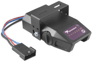
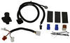
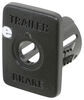
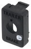
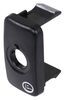
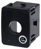
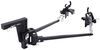
This proportional brake controller is designed to keep towing simple. Includes an LED braking indicator, a slide-bar manual override, and a knob to adjust braking power. Mounts easily within a 90-degree vertical range.
Features:
Specs:
Once the brake controller is installed, you can use the knob on the right side of the unit to adjust the gain (also known as output). Gain lets you set the maximum amount of power that will be applied to your trailer's brakes. You want to set it as high as you can without locking up the brakes. Typically, this setting is only readjusted when you experience changing road conditions or if you switch over from a heavy, loaded trailer to a much lighter, empty trailer, or vice versa.
You can fine-tune the gain by adjusting the sensitivity of the internal sensor using the knob on the left side. This controls the aggressiveness of your trailer's braking, meaning how quickly the brakes reach the maximum braking level. You can adjust this when you're towing heavy loads and you need more umph to bring your trailer to a stop. Your tow vehicle doesn't need that much power to brake in time, but your heavy trailer does. A high sensitivity level will get the braking power to your trailer brakes faster and with more intensity so that it doesn't push your tow vehicle forward.
LED Indicator
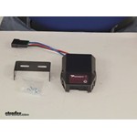
Keeping with its simple design, the Voyager will not overwhelm you with information. An LED indicator on the top of the unit lights up green to show that your trailer is securely connected to your tow vehicle. The LED indicator will change to red when the brakes on your trailer are activated.
During installation and setup, this light is also used to ensure that the Voyager will be able to function correctly. Proper leveling of the internal sensor is crucial to the operation of this brake controller. When the sensor is level, the LED will change to a shade of orange.
The Voyager is designed to be mounted in your cab at a vertical angle that is between -20 degrees and 70 degrees. The brake controller needs to be horizontally level and parallel to the direction of travel in order to function properly.
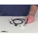
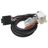
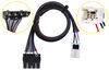
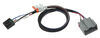
To connect the Voyager, just plug the included harness into your vehicle. The other end plugs into the controller - no hardwiring required.
Once the controller is mounted and connected, you must level the internal sensor. First, set the overall power to the maximum using the knob on the side of the controller. Then, while pressing the tow vehicle's brake pedal, adjust the level knob on the other side of the brake controller (this is the same knob that is used to fine-tune the power output) until the LED monitor is a shade of orange.
Note: If you don't already have a 7-way plug at the back of your vehicle, take a look at our exclusive 7- and 4-way brake controller installation kit (ETBC7 - sold separately).
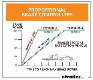
The Tekonsha Voyager brake controller comes equipped with proportional braking to give you the best towing experience. Proportional braking means that your trailer brakes mimic your tow vehicle's brakes. If you slam on the brakes in your vehicle, your trailer brakes will activate with the same intensity; if you brake lightly, your trailer brakes lightly too. The trailer's braking is in proportion to your vehicle's braking. This saves wear and tear on the tires and the brakes on both your vehicle and trailer.
The Voyager uses a pendulum system to sense how your vehicle is braking so it can send the right amount of braking power to your trailer. It measures the inertia of your tow vehicle and activates the trailer's brakes to slow at the same rate. The result is uniform braking across your towing setup. No push-pull action - just smooth, proportional braking every time.
 Alternate Instructions
California residents: click here
Videos are provided as a guide only. Refer to manufacturer installation instructions and specs for complete information.
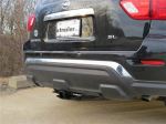
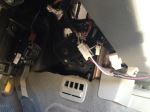
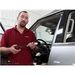
Today on this 2011 Nissan Pathfinder we're going to install part number 39510 from Tekonsha. This is the Voyager trailer brake controller. This vehicle has already been equipped with a 4-pole wiring packaging from the factory. To add our brake controller and connector, we're basically going to just fill in the blanks. We're going to start off underneath the dash. We're going to locate the tow package port underneath the dashboard which is going to be just right of the steering wheel, behind the dash, and also a little bit above the diagnostic port. We'll go ahead and take the adapter cord and plug it into the brake controller, and then we'll go ahead and plug it into the port underneath the dash. The part number for our adapter cord will be3050-P.
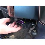
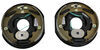
With all the brake controller wires plugged together, we'll go ahead and add the bracket to the dashboard underneath. We're going to locate it next to the diagnostic port, just a little bit to the left of it. We'll use two screws to attach the bracket to the dashboard. Next we'll pre-drill the holes in our brake controller to accept the hardware; we'll install the brake controller to your bracket using four more screws; and then we'll go ahead and take a moment to zip tie our wires and make sure they're safe and out of the way. Then we can go to the back of the vehicle. That's where we're going to go ahead and add our 7-pole connector to the back of the vehicle.
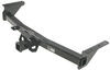
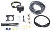
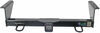
That's going to be part number 37185. We're going to take the bracket and hold it to the bottom of the hitch. There's an existing weld nut we're going to use to fasten it to the hitch. We'll hold it up there, make a mark on the bracket, and then we'll go ahead and drill it out to a 3/8 hole. We'll take our bracket back to the vehicle and attach it to the hitch, using an 8 mm bolt, the 1.25 thread hitch; then we'll go and add our 7-pole connector. On the 4-pole end of it we're going to apply some dielectric grease and then attach it to the factory 4-pole.
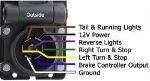
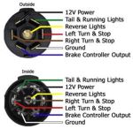
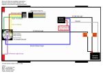
We're going to run a zip tie through the wires to make it a semi-permanent connection. We'll take a moment to tape up our wires and also add our loom material to help protect some of the wires and make it look nice. At this point we'll go ahead and connect the 7-pole to the bracket, and then we're going to add a length of wire to it about 3 or 4, part number 10-2-1. We'll cut the sheath back and we'll have a black and a white wire. We'll run our black wire to the black wire on the 7-pole connector and our white wire to the blue wire on 7-pole connector. We'll crimp those down and then use some tape to help protect them.There are two remaining wires left.
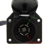
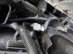
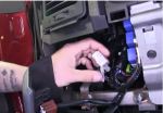
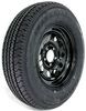
There'll be a white wire for the ring terminal and a purple wire for the butt connector. We're going to tape those two wires to our grey cable, and we'll run those wires along with the grey cable. Now we're going to route our cables over to the end of the tow package which is located next to the spare tire. We'll measure a length of a grey duplex cable we need and cut the excess off; then we'll strip back to the sheath of the grey cable, exposing the wires we'll need later. Then we can take the white wire with your ring terminal and ground it to the frame. The self-tapping screw we'll be using will be part number SA1131822. We're going to look for a connector that's at the end of our tow package. We've got a small connector with two wires going to it. There will be a brown wire and a purple wire going to it. Now,we don't have a connector to match that, so we'll rotate the connector and remove it from the wires; then we'll go ahead and crimp our wires from our grey cable to those two wires. We'll use a butt connector to make those connections. Our part number for our butt connectors we'll be using will be part number 05732-2. We're going to connect this as follows. Our white wire which will be our brake controller output is going to connect up to the brown wire; and then our other wire, a black wire, will connect up to the purple wire. That'll be our 12 volt power supply. We'll go ahead and tape up our connections and zip tie our wires safe and out of the way. All our connections are done at the back of the vehicle; now we'll go underneath the hood and we have to add one relay to power our 12 volt power supply. There's a relay box closest to the battery. We'll remove the lid and you'll see that there's two relays already installed, and there'll be an open socket for an additional relay. We'll install the relay for our 12 volt power supply, and that's going to included in the kit part #C57000. With all of our connections made, we'll go ahead and test out the brake controller. We'll plug a trailer into it and you'll see that the LED on top will turn from off to a green color; and then we'll use the manual override. You'll see that goes from a green, to a yellow, to a red that shows the manual output works. Now we'll go ahead and try the foot brake. We have to make the level in the brake controller a little bit more aggressive, so we can see it work. Push down the brake pedal and you can see that turns from a green to an orange. And with that, that'll finish it for our install of our Voyager brake controller on our 2011 Nissan Pathfinder.


Do you have a question about this Trailer Brake Controller?
Info for this part was:
At etrailer.com we provide the best information available about the products we sell. We take the quality of our information seriously so that you can get the right part the first time. Let us know if anything is missing or if you have any questions.


Thank you! Your comment has been submitted successfully. You should be able to view your question/comment here within a few days.
Error submitting comment. Please try again momentarily.