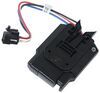
Tekonsha Primus IQ Trailer Brake Controller w/ Custom Harness - Up to 3 Axles - Proportional


To see if this custom-fit item will work for you please tell us what vehicle you'll use it with.


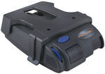
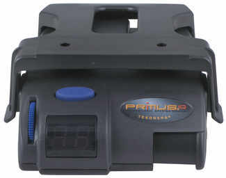
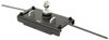
This proportional brake controller has simple controls and a digital display for diagnostic information. Includes 3 boost levels, a slide-bar manual override, built-in battery protection, automatic leveling, and continuous diagnostics.
Features:
Specs:
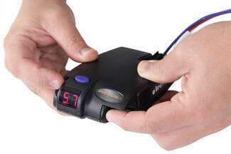
You can adjust the gain (also known as output) with the thumbwheel on the front of the controller. Gain lets you set the maximum amount of power that will be applied to your trailer's brakes. A heavier trailer will need more power to achieve smooth, safe braking, while a lighter trailer will need less. Typically, the gain is only readjusted when you experience changing road conditions or if the weight of your trailer changes.
The boost setting controls the aggressiveness of your trailer's braking, meaning how quickly the brakes reach the maximum braking level. You can adjust this when you're towing heavy loads and you need more umph to bring your trailer to a stop. Your tow vehicle doesn't need that much power to brake in time, but your heavy trailer does.
Depending on the level of boost, your trailer brakes can start at either 13 percent or 25 percent of the set gain. What this means is that, instead of starting at 0, the brakes will start at 25 percent and get to 100 percent sooner. This keeps the trailer from pushing your tow vehicle forward.
If your trailer weighs less than your tow vehicle, no boost is needed. But, if you want your trailer to lead the braking, you can select level B1.
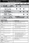
Boost Levels:
| Approximate Gross Trailer Weight | Boost Level | Increase in Initial Power Output |
|---|---|---|
| Less than tow vehicle GVW | B1 | 13% |
| Equal to tow vehicle GVW | B1 or B2 | 13% or 25% |
| Up to 25% more than tow vehicle GVW | B2 or B3* | 25% |
| Up to 40% more than tow vehicle GVW | B3* | 25% |
*Both B2 and B3 offer a 25-percent boost in initial power. But the braking curve for B3 is more aggressive than that of B2. This means that, even though you will start out with the same intensity when using these boost levels, you will get an overall more aggressive braking experience with the higher level. So if you use B3, you will reach maximum braking sooner than if you use B2.
To adjust the boost, use the blue push-button on the top of the Primus IQ.
The Tekonsha Primus IQ comes with an easy-to-reach, slide-bar manual override, great for stopping sway or controlling your trailer's momentum in emergencies. To engage the manual override, just push the slide-bar to the left, towards the center of the controller. This will activate the trailer's brakes and brake lights without you having to apply the brakes on your tow vehicle, perfect for limiting trailer movement while you're cruising.
The Primus IQ can mount between -90 degrees and 90 degrees vertically, but the brake controller still needs to be horizontally level and parallel with the direction of travel.
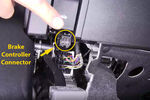
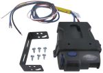
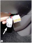
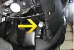
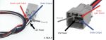
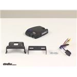
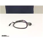
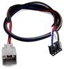
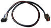
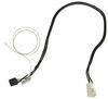
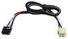
After mounting the Primus IQ unit in your cab using the included bracket, simply plug the included custom harness into your vehicle. The other end of the harness plugs into the brake controller. To remove the IQ for storage when you're not using it, just unplug the unit and slide it out of the bracket. With a replacement wiring harness (sold separately) and replacement bracket (6927 - sold separately), you can even transfer the IQ to another vehicle.
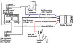
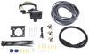
Note: If you don't already have a 7-way plug at the back of your vehicle, take a look at our exclusive 7- and 4-way brake controller installation kit (ETBC7 - sold separately).
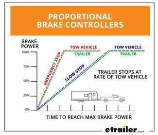
The Tekonsha Primus IQ brake controller comes equipped with proportional braking to give you the best towing experience. Proportional braking means that your trailer brakes mimic your tow vehicle's brakes. If you slam on the brakes in your vehicle, your trailer brakes will activate with the same intensity; if you brake lightly, your trailer brakes lightly too. The trailer's braking is in proportion to your vehicle's braking. This saves wear and tear on the tires and the brakes on both your vehicle and trailer.
The Primus IQ uses an internal inertia sensor to detect how your vehicle is braking so it can send the right amount of braking power to your trailer. It measures the inertia of your tow vehicle and activates the trailer's brakes to slow at the same rate. The result is uniform braking across your towing setup. No push-pull action - just smooth, proportional braking every time.
 Alternate Instructions
California residents: click here
Videos are provided as a guide only. Refer to manufacturer installation instructions and specs for complete information.
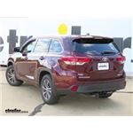
Speaker 1: Today on our 2017 Toyota Highlander, we'll be having a look and installing the Tekonsha Primus IQ Trailer Brake Controller, part number TK90160. To use our installation, we'll be using the etrailer ETBC7 kit, part number ETBC7. Here's what our brake controller looks like installed. As you can see, this is a nice compact unit. What this will allow us to do will be control electric trailer brakes on up to 3 axles on our trailer, allowing us to have a smoother and safer stop.Now what's great about this brake controller compared to others, this is a proportional unit. It's not time delayed so we don't have to worry about waiting for the brakes to activate on our trailer.
They will activate immediately once we start to slow down in our Highlander. This is a very simple brake controller to operate, which makes it one of our favorites on our website. Over there to the right, we have our main override. What this will allow us to do is apply the brakes on our trailer only, without applying brakes in our Highlander. If we get in a situation where our trailer starts to get sideways behind us, it starts to jack-knife, we can slow it down by sliding the actuator on over, allowing us to brake just the trailer.Now you can see when you just start gradually going up on the actuator, it starts to apply more and more power, so depending on how far over you slide it, that's how much power you're getting.
Over here to our left, this is our gain adjustment knob. This controls how much power is being applied to the trailer brakes at any moment in time. We slide our main override all the way over, you can see it goes up to 11. We start moving this knob down, it will start counting down 8.1, 5.6, all the way to zero. Zero being no power being applied, 11 being the maximum applied.
The general rule of thumb, start off with it somewhere right in the middle. In our case, 5 1/2 or 6 is right in the middle, so that way you can adjust as needed for your comfort level and your safety.The button here on the top, this is our boost level button. What boost means is it's adding more power to the brakes and applying them faster initially, so you get a quicker response time, so if you suddenly have a heavier load or start driving mountainous terrain and you need more braking, just press the button once and you can get into your boost mode. There's 3 different settings. Right now we're in boost 1.
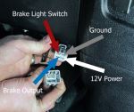
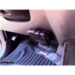
Press it again, on boost 2, again, boost 3. The higher you go on the boost level settings, the more power and the faster the brakes are responding to you. Then if you press it again, you can turn it off so there is no boost mode.What sets this brake controller apart from others on the market is that this is a very high quality unit at an affordable price because it gives you the safety and the important features that you need, without having a lot of extra bells and whistles to over-complicate it and make it more difficult to use. Now that we've gone over some features, we'll show you how to get it installed. To begin our install, the first thing that we're going to want to do is ensure that our vehicle already has a 4 pole, flat trailer wiring harness installed and that it's working properly.Now we'll take our 7 way and the 7 way bracket, and we'll mount our 7 way to the bracket using the provided hardware. There's a screw that goes through the front and then a star nut on the back. Now we'll hold the nut still with a wrench and we'll tighten the screw up with a screwdriver. We'll do this for all 4 of our screws. In order to attach our 7 way to our vehicle, we need to have a bracket that we can wrap around our hitch. This is a Curt No Drill Long Bracket. It's part number C57202 on our website. We'll use the provided hardware to secure the 2 together and we'll tighten those down using our wrench and our screwdriver again. We'll take our assembled 7 way and the bracket, slide it over the hitch, and we'll use the hose clamp to secure it to the hitch. We use a 5/16 nut driver to tighten the clamp down. Now we'll use a pair of tin snips to cut the excess of our clamp off.Now we have 2 options here. We can just simply plug in our 7 way to our existing 4 pole flat or what we can do is cut off the connectors and use heat treated butt connectors together to combine all the wires so we don't have to worry about any possible corrosion over the course of time. That's what we're going to do today. We'll separate our wires a little bit further, just strip them all back. We'll put on some 14 to 16 gauge heat treat butt connectors, which we have available on our website and crimp them down. The reason you want to use these, they will help prevent corrosion and provide us a better weather tight seal than just the standard 4 pole flat connection would, so we'll make it last a very long time and avoid any future electrical problems that could potentially occur.Now we'll cut off the standard butt connectors from our black and blue wires. The reason we're doing this, we're going to replace those with heat treat butt connectors as well. For these we will use a 10 to 12 gauge heat treat butt connector. The purple wire we have here, we're not going to use this in our application. This is for a reverse signal input. If you have a boat trailer that has a reverse lockout solenoid for the surge brakes, you would need this wire, but in our instance we're not using it, so we're just going to cut it off so we don't have to worry about having a loose wire hanging around. We've gone ahead and passed our 4 pole flat wiring that exists through a spot here of our fascia support, and we have our wires that go off of our 7 way over our hitch. This way, we can conceal them easier.Now we'll just match up our colors, so we'll match our green wires together. These are for our right turn signal and right brake light. Do the yellow one next, that's for our left turn signal and left brake light. Then we'll do the brown, that's for our taillight and running light circuit. This white wire here, this is our ground wire that was off of our vehicle's existing 4 pole flat wire. The ground wire off of our 7 way has a ring terminal. We can do 1 of 2 things. We can attach this to the vehicle's sheet metal with a self-tapping screw, which comes with our kit, or we can combine the two wires, which is what I like to do because it does use an existing ground that's already in the vehicle, and because it's a cleaner install. We'll measure off how much we're going to need, cut off the excess, inaudible 00:07:34 the installation. Use one of our heat treat butt connectors, crimp it together.The gray wire that comes with our kit is a duplex wire. What that means is there's 2 separate wires inside the outer gray sheathing. I'll take a utility knife, go down the middle, being careful not to cut the wires inside, pull back the insulation and then we'll find a black and a white wire. We'll cut back the insulation from both of those. The black wire, we'll attach to our black wire. This will be our constant 12 volt power source to our 7 way. The white wire will go to our blue wire. This is for our electric trail brake output. Now we'll use a heat gun, which we have available on our website, to shrink down our butt connectors. The reason we're going to use a heat gun versus a lighter or another source of heat is it provides an indirect source of heat versus direct flame, and it won't damage the butt connectors.Okay, we've bundled up our excess wire to our fascia support tab here with a zip tie, and we went ahead and routed our gray duplex wire towards the front of the vehicle, making sure we avoided any moving parts or sources of heat. We went up and above our rear sub-frame to keep away from any moving parts of our suspension or our rear drive line. Comes out over our sub-frame, we have it zip tied to a bracket for our parking brake cable, and goes underneath this panel here towards the front, and it comes out and is zip tied to this bracket right here. Goes up right toward our firewall and zip tied to a bracket which holds an oxygen sensor wire in place. Now we'll drop down a pull wire from the engine bay.Today we're using a piece of air line tubing as our pull wire. Anything that you have that's somewhat stiff but yet still flexible work great. A coat hanger would even work. Shove it behind our air box here and it will go on down to where we need it. Here's where our pull wire came down. We already went ahead and taped our duplex wire to it so we can bring it inside our engine bay. We went ahead and secured up our wire with the zip tie to a wiring harness here to avoid any slack falling down into our engine bay, and removed the sheathing from the end of our wires.Now we need to find a spot to mount our circuit breakers. If remove this panel right here by our driver's side headlight, be easy to do. We have 2 plastic push pin fasteners, 1 in each corner. The way these work is if we get a flathead screwdriver underneath the center section it will pop up and the whole pin can be pulled out. Okay, these are our circuit breakers here and here. We have a 30 amp one and a 40 amp one. The 40 amp one will be used to power our constant 12 volt outlet on the back of the 7 way. That gets our black wire that we brought, and the white wire is for our brake controller, that goes inside the vehicle. The 30 amp one, that will power our brake controller itself. We'll secure these to the vehicle with our provided self-tapping screws.We're measuring off how much black wire we need right now to connect to the silver side of our 40 amp breaker. We'll cut off the excess, making sure we keep it. We'll strip off some of the insulation from our black wire, take one of our small yellow ring terminals, and we'll crimp it down, remove the nut from the terminal. Place the wire onto the stud, reinstall the nut. We're looking at the underside of the driver's side dashboard right now. We need to gain access to our brake light switch and our firewall so we can pass our wires through. Now we're going to take this panel down here in order to gain access to our brake light switch. In order to do that, we have a Phillips screw on each corner of it. Pull down on the panel. Now in order to get this panel all the way out of the vehicle so it's out of our way, we have a connector here for our tire pressure monitoring system reset button. Push on this tab, pull back. We can use a trim panel tool to pop the wiring clips off the panel. The panel's free. It's out of our way.We need to make access to get to the firewall. Peel our carpet back and we'll take a utility knife here and notch through some of this insulation and the carpet behind it. Now with a small drill bit, we'll drill a pilot hole right in this area here. Now we're going to install a grommet in the hole that we drilled in the fire wall, and we'll enlarge our hole to fit the appropriate size for our grommet. Place our grommet into the hole. We'll take our black wire that we cut the excess off of, strip back one end of insulation, stick on one of our small ring terminals, crimp it down, place the wire onto the stud on the breaker. That's the 30 amp that will supply power to our brake controller on the silver stud. Okay, now we'll drop our black wire that we attached to the breaker, and our white wire that we pulled up earlier, back behind our firewall, following the same path as our duplex wire, so we can pull it into our grommet that we installed.Now I stuck an air line tubing through our grommet to use as a pull wire to bring those wires inside of our passenger compartment. Now I'll pull our 2 wires into our vehicle. Now we'll cut off the excess from our white and our black wire. We'll strip both back, stick on 2 of our yellow butt connectors that come with the brake controller, take our brake controller harness, the blue wire that goes to our white wire. That was our output for our trailer brakes. The black wire, that's our constant 12 volt power that powers our brake controller, that will go to our black wire. Okay, now we'll take some of our leftover white wire, strip it back, take one of our butt connectors, stick it on, take the white wire off our brake control harness, strip back just a little bit more insulation, take that inside, crimp it down. We'll pass the end of that white wire through our grommet with the air line tubing, leading it through and this will go back to our engine compartment.We've got our wire down now. Now we'll take our pull wire and we'll route this the same way, just up towards our engine bay. Okay, we pulled the white wire all the way up into the engine bay. We've gone ahead and zip tied up the white wire to our wiring harness here again, to take care of any slack from falling down. We measured off how much we we're going to need to connect to our negative battery terminal right here. This is our ground wire. Strip it back, take one our large, yellow ring terminals, stick it on the wire, crimp it down. We'll move this nut right here. It's 12 millimeter. Stick the terminal over that stud, reinstall the nut. Clamp it down. Our leftover black wire here, strip back the insulation from one end, put one of our small ring terminals on, crimp it down. We'll attach this to 1 of our breaker's gold side, which goes to our battery. It doesn't matter which one. They both will have a wire going to our battery. Tighten all of our nuts up with a 10 millimeter socket. Pull this over to our positive battery terminal, over here. Measure out how much we need, cut off the excess, strip back the insulation. We'll add a large ring terminal and we'll crimp it into place, and we'll do the same for our other breaker now. It will go onto our breaker's last battery terminal post.Measure off how much we need to make our connection to the positive post, strip back the insulation, crimp on our large ring terminal, take both of our ring terminals now and place them underneath this 12 millimeter nut, and tighten that down. Now we'll replace our side cover here and put our battery cover back on, the positive post. Now we need to make our connection with our red wire off of our brake control harness to the cold side of our stoplight switch, which we can find in the upper portion of our brake pedal, underneath the dash. This black cylinder that I'm pointing to, that has a brown section with an adjustable nut and plunger, this is our brake light switch. I've already stripped back some of the wire loom to expose the wires that go to it.Now what a cold side means is there's no power going to it unless the brake pedal is depressed, so we'll use a test light to determine which wire is our cold side. I'll press in the brake pedal. You can see when I press the brake pedal I get signal, so what I'll do to make it easier to see, I will press a tab on the side of the electrical connector, unplug the harness and pull it down. This is the tab right here. Now the wire that we found was the cold side was our thickest wire. It's a green wire right here by itself, so we'll cut this wire, just strip back the insulation from both ends that we just cut. I have a smaller segment of red wire here. You can pick this up on our website. It's part number 16-1-1. It's sold by the foot, 16 gauge wire. You only need about a foot. We'll strip off the insulation from one end and we'll tie it together with the end of one of our green wires. We'll stick on a yellow butt connector and we'll crimp it down. Our other end, I stripped back a little long so I could pull it back on itself to make it thicker. I'll stick that end to the butt connector and I'll crimp it down.Now we'll plug our brake light switch back in. Now we'll strip back the installation from our red wires, place on a blue butt connector, crimp it down. Now we need to find an appropriate place to mount our brake controller. To the right side of our dash is the best spot because it won't interfere as we're getting in and out of the vehicle. We want to pay attention though that we don't screw into our airbag for our knees right here. Get as far away from that as possible so you can, but still enough room for you to get the screws in place, so right here's good. Be sure it's level. Take our bracket, screw the bracket in. Take our brake controller, plug our harness into it. Now we'll slide our brake controller into position on the bracket, and use our screws that come with it to secure it to our bracket. Now we'll use a right angle screwdriver to get the other one in place.Okay, we secured up our wiring with a zip tie to part of the dash to keep it away from our feet. Now we can re-install our panel underneath. Make sure we plug back in our sensor, and it goes back in the same way. As you can see, once we put our panel back up underneath, it pushed our wires back into the proper place. They won't be in contact with our feet as we drive. We went ahead and sealed up around our grommet with some sealant. We have that available on our website if you'd like to purchase some. Now we'll go ahead and hook our trailer up to our vehicle to make sure the brake controller works. When we hook up to it, you can see a C be displayed on our screen for the brake controller, meaning that we have a proper connection and everything's working properly.That completes our look at and installation of the Tekonsha Primus IQ Trailer Brake Controller, part number TK90160 with the etrailer ETBC7 kit, part number ETBC7 on our 2017 Toyota Highlander.

Easy to install and very affordable.
Quick install works Great
Worked great!
easy to install
Just what the doctor ordered. Thanks
The package arrived on time (actually a day early!). It came with the correct Harness. It was easy to install and is working properly!
Great for the price
Ordered as replacement for one that quit after 18 years. New plugged into existing wiring and even fits in existing mounting bracket. So far so good.

was easy to install and works great
Easy to hook up , works flawlessly
Simple hook-up when using the model specific harness.
Easier to install than expected. Works flawlessly
Very easy installation.
Easy to install and works great no issu es


Do you have a question about this Trailer Brake Controller?
Info for this part was:
At etrailer we provide the best information available about the products we sell. We take the quality of our information seriously so that you can get the right part the first time. Let us know if anything is missing or if you have any questions.


Thank you! Your comment has been submitted successfully. You should be able to view your question/comment here within a few days.
Error submitting comment. Please try again momentarily.