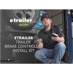
Expert Review Video:
Trailer Brake Controller Specs:
Features:
This is one of our favorite brake controllers, with flawless braking and a tiny dash knob that looks like it came straight from the factory. It's so easy to adjust your settings or activate manual override.
Installation Notes:
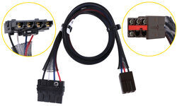
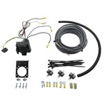
You will also need item 37185 ($41.04) to complete your wiring.
Tech Tip:
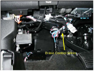
An additional length of wire may be necessary to connect the 7-Way socket of part 37185 to the vehicle's tow package wires which are along the rear frame rail.
More Information >Trailer Brake Controller Specs:
Features:
This is one of our favorite brake controllers, with flawless braking and a tiny dash knob that looks like it came straight from the factory. It's so easy to adjust your settings or activate manual override.
Installation Notes:
The brake controller can easily be installed with the included vehicle specific wiring adapter; no other parts are necessary.
More Information >Trailer Brake Controller Specs:
Features:
This is one of our favorite brake controllers, with flawless braking and a tiny dash knob that looks like it came straight from the factory. It's so easy to adjust your settings or activate manual override.
Installation Notes:
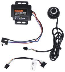
You need item ETBC7 ($118.67) to install your controller.
You may also need a 4-Flat connector to complete your wiring.
More Information >Trailer Brake Controller Specs:
Features:
Towing? There's an app for that. This brake controller connects to your phone with Bluetooth so all your settings are right in your hand. The unit plugs into your 7-way for a one-step installation with no wiring.
Installation Notes:
You will also need item 37185 ($41.04) to complete your wiring.
Tech Tip:
An additional length of wire may be necessary to connect the 7-Way socket of part 37185 to the vehicle's tow package wires which are along the rear frame rail.
More Information >Trailer Brake Controller Specs:
Features:
Towing? There's an app for that. This brake controller connects to your phone with Bluetooth so all your settings are right in your hand. The unit plugs into your 7-way for a one-step installation with no wiring.
Installation Notes:
More Information >Trailer Brake Controller Specs:
Features:
Towing? There's an app for that. This brake controller connects to your phone with Bluetooth so all your settings are right in your hand. The unit plugs into your 7-way for a one-step installation with no wiring.
Installation Notes:
You need item ETBC7L ($95.88) to install your controller.
You may also need a 4-Flat connector to complete your wiring.
More Information >Trailer Brake Controller Specs:
Features:
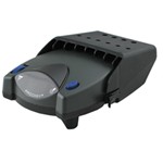
This unique brake controller mounts on your trailer instead of in the cab so you can tow your trailer using any truck. You'll control your settings from the handy key fob remote.
Installation Notes:
You will also need item 37185 ($41.04) to complete your wiring.
Tech Tip:
An additional length of wire may be necessary to connect the 7-Way socket of part 37185 to the vehicle's tow package wires which are along the rear frame rail.
More Information >Trailer Brake Controller Specs:
Features:
This unique brake controller mounts on your trailer instead of in the cab so you can tow your trailer using any truck. You'll control your settings from the handy key fob remote.
Installation Notes:
More Information >Trailer Brake Controller Specs:
Features:
This unique brake controller mounts on your trailer instead of in the cab so you can tow your trailer using any truck. You'll control your settings from the handy key fob remote.
Installation Notes:
You need item ETBC7L ($95.88) to install your controller.
More Information >Trailer Brake Controller Specs:
Features:
This is one of our favorite brake controllers, with flawless braking and a tiny dash knob that looks like it came straight from the factory. Its unique off-roading mode helps you handle rough conditions, so get out there and get towing.
Installation Notes:
You need item ETBC7 ($118.67) to install your controller.
You may also need a 4-Flat connector to complete your wiring.
More Information >Trailer Brake Controller Specs:
Features:
This is one of our favorite brake controllers, with flawless braking and a tiny dash knob that looks like it came straight from the factory. Its unique off-roading mode helps you handle rough conditions, so get out there and get towing.
Installation Notes:
The brake controller can easily be installed with the included vehicle specific wiring adapter; no other parts are necessary.
More Information >Trailer Brake Controller Specs:
Features:
This is one of our favorite brake controllers, with flawless braking and a tiny dash knob that looks like it came straight from the factory. Its unique off-roading mode helps you handle rough conditions, so get out there and get towing.
Installation Notes:
You will also need item 37185 ($41.04) to complete your wiring.
Tech Tip:
An additional length of wire may be necessary to connect the 7-Way socket of part 37185 to the vehicle's tow package wires which are along the rear frame rail.
More Information >Trailer Brake Controller Specs:
Features:
This compact brake controller fits nicely in your cab. It's designed to mount flush to the dash and is only 1" thick. The controls are simple, the LED display is large and bright, and the manual override is easy to reach in a pinch.
Installation Notes:
The brake controller can easily be installed with the included vehicle specific wiring adapter; no other parts are necessary.
More Information >Trailer Brake Controller Specs:
Features:
This compact brake controller fits nicely in your cab. It's designed to mount flush to the dash and is only 1" thick. The controls are simple, the LED display is large and bright, and the manual override is easy to reach in a pinch.
Installation Notes:
You need item ETBC7 ($118.67) to install your controller.
You may also need a 4-Flat connector to complete your wiring.
More Information >Trailer Brake Controller Specs:
Features:
This compact brake controller fits nicely in your cab. It's designed to mount flush to the dash and is only 1" thick. The controls are simple, the LED display is large and bright, and the manual override is easy to reach in a pinch.
Installation Notes:
You will also need item 37185 ($41.04) to complete your wiring.
Tech Tip:
An additional length of wire may be necessary to connect the 7-Way socket of part 37185 to the vehicle's tow package wires which are along the rear frame rail.
More Information >Trailer Brake Controller Specs:
Features:
This compact brake controller fits nicely in your cab. You can mount it anywhere you like and it's only 1" thick. The LED display keeps it simple with bar indicators, while the large manual override is easy to reach in a pinch.
Installation Notes:
You need item ETBC7 ($118.67) to install your controller.
You may also need a 4-Flat connector to complete your wiring.
More Information >Trailer Brake Controller Specs:
Features:
This compact brake controller fits nicely in your cab. You can mount it anywhere you like and it's only 1" thick. The LED display keeps it simple with bar indicators, while the large manual override is easy to reach in a pinch.
Installation Notes:
The brake controller can easily be installed with the included vehicle specific wiring adapter; no other parts are necessary.
More Information >Trailer Brake Controller Specs:
Features:
You can stick the control knob to the dashboard, plug in the module, and your brake controller installation is done with no drilling and no hardwiring. The knob is large and easy to use, while the main unit is out of sight behind the dash.
Installation Notes:
You need item ETBC7 ($118.67) to install your controller.
You may also need a 4-Flat connector to complete your wiring.
More Information >Trailer Brake Controller Specs:
Features:
You can stick the control knob to the dashboard, plug in the module, and your brake controller installation is done with no drilling and no hardwiring. The knob is large and easy to use, while the main unit is out of sight behind the dash.
Installation Notes:
You will also need item 37185 ($41.04) to complete your wiring.
Tech Tip:
An additional length of wire may be necessary to connect the 7-Way socket of part 37185 to the vehicle's tow package wires which are along the rear frame rail.
More Information >Trailer Brake Controller Specs:
Features:
Towing? There's an app for that. This brake controller connects to your phone with Bluetooth so all your settings are right in your hand. Plus, it's plug-and-play, so no splicing and no permanent alteration to your vehicle.
Installation Notes:
You will also need item 37185 ($41.04) to complete your wiring.
More Information >Trailer Brake Controller Specs:
Features:
This compact brake controller fits nicely in your cab. You can mount it anywhere you like and it's only 1" thick. The LED display is large and bright so it's easy to see, while the large manual override is easy to reach in a pinch.
Installation Notes:
You will also need item 37185 ($41.04) to complete your wiring.
Tech Tip:
An additional length of wire may be necessary to connect the 7-Way socket of part 37185 to the vehicle's tow package wires which are along the rear frame rail.
More Information >Trailer Brake Controller Specs:
Features:
This compact brake controller fits nicely in your cab. You can mount it anywhere you like and it's only 1" thick. The LED display is large and bright so it's easy to see, while the large manual override is easy to reach in a pinch.
Installation Notes:
You need item ETBC7 ($118.67) to install your controller.
You may also need a 4-Flat connector to complete your wiring.
More Information >Trailer Brake Controller Specs:
Features:
This compact brake controller fits nicely in your cab. You can mount it anywhere you like and it's only 1" thick. The LED display is large and bright so it's easy to see, while the large manual override is easy to reach in a pinch.
Installation Notes:
The brake controller can easily be installed with the included vehicle specific wiring adapter; no other parts are necessary.
More Information >Trailer Brake Controller Specs:
Features:
Towing? There's an app for that. This brake controller connects to your phone with Bluetooth so all your settings are right in your hand. The plug-and-play unit mounts under your dashboard, out of sight and out of your way.
Installation Notes:
You need item ETBC7 ($118.67) to install your controller.
You may also need a 4-Flat connector to complete your wiring.
More Information >Trailer Brake Controller Specs:
Features:
Towing? There's an app for that. This brake controller connects to your phone with Bluetooth so all your settings are right in your hand. The plug-and-play unit mounts under your dashboard, out of sight and out of your way.
Installation Notes:
The brake controller can easily be installed with the included vehicle specific wiring adapter; no other parts are necessary.
More Information >Trailer Brake Controller Specs:
Features:
Towing? There's an app for that. This brake controller connects to your phone with Bluetooth so all your settings are right in your hand. The plug-and-play unit mounts under your dashboard, out of sight and out of your way.
Installation Notes:
You will also need item 37185 ($41.04) to complete your wiring.
Tech Tip:
An additional length of wire may be necessary to connect the 7-Way socket of part 37185 to the vehicle's tow package wires which are along the rear frame rail.
More Information >
 Filters