To see if this custom-fit item will work for you please tell us what vehicle you'll use it with.

Thank you! Your comment has been submitted successfully. You should be able to view your question/comment here within a few days.
Error submitting comment. Please try again momentarily.
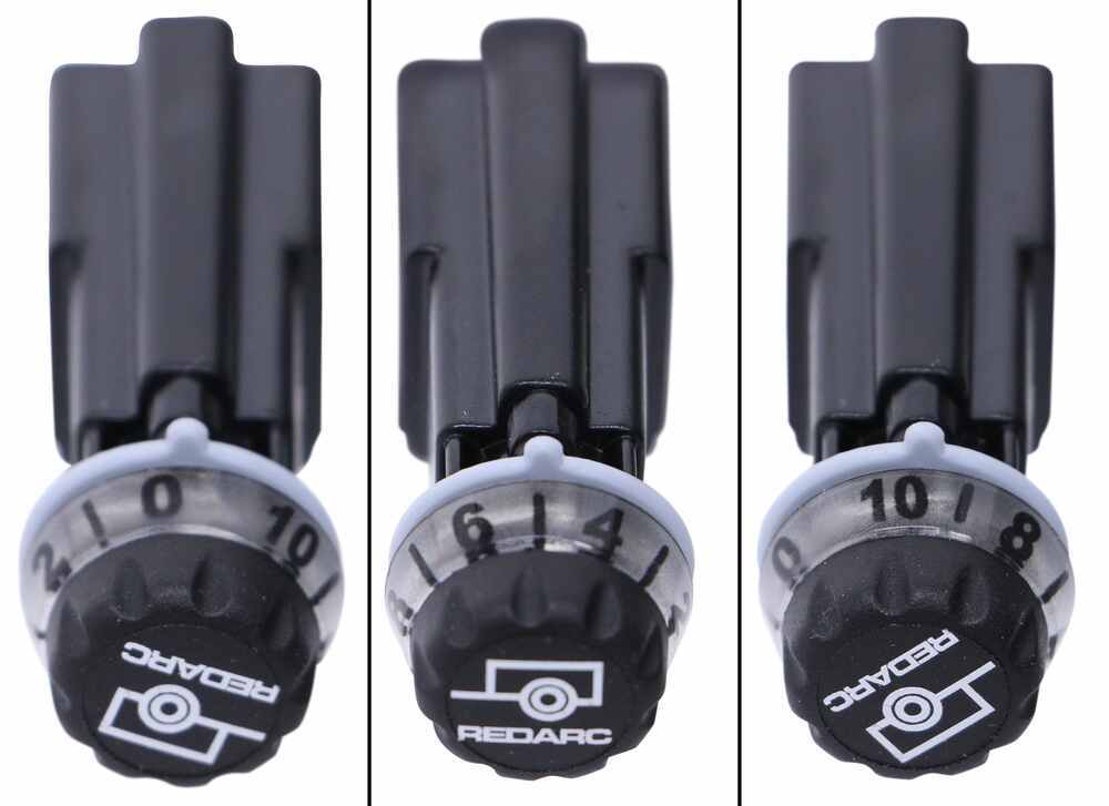
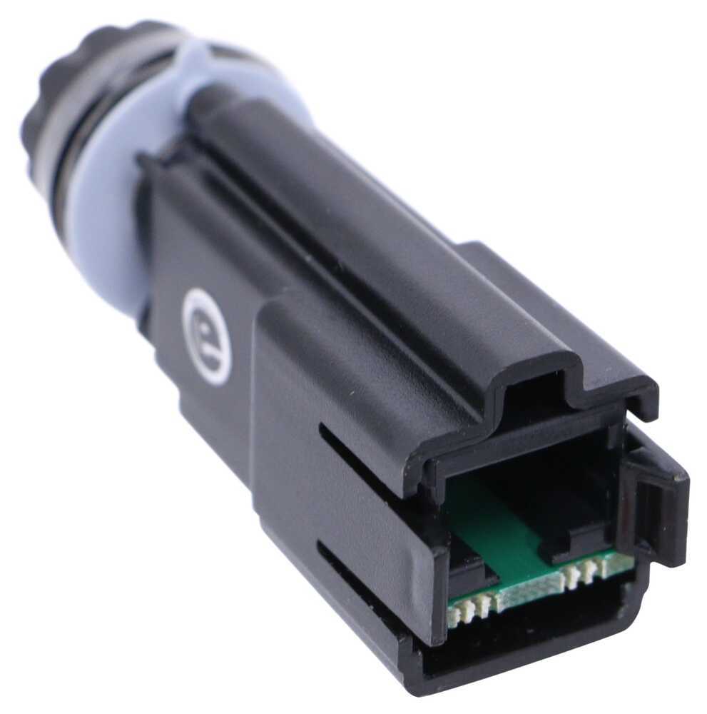
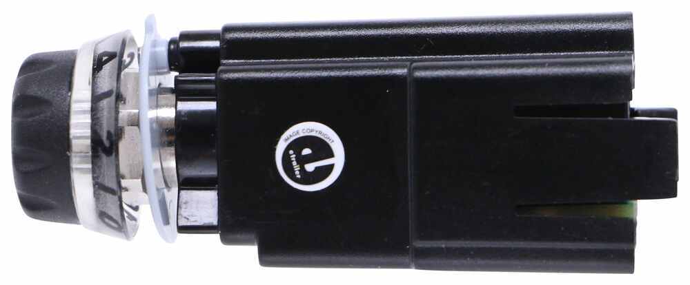
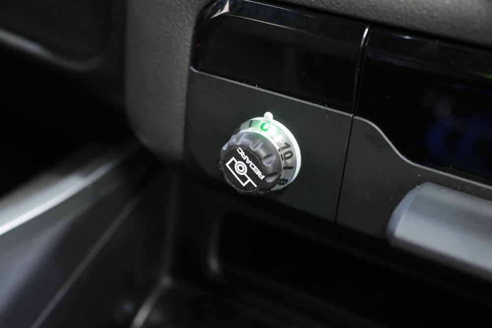
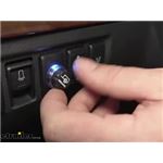
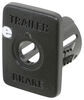
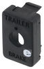
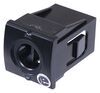
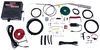
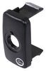
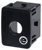
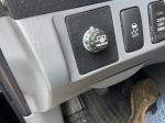
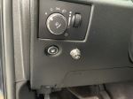
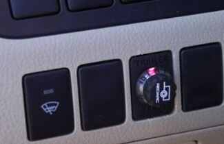
Most brake controllers stick out and take up knee room, but this one mounts the main unit completely out of sight behind the dash. All you see is a small knob on the console, just 1-7/8" long and 9/16" wide. It blends right in, looking like it came from the factory instead of an add-on box under your steering wheel. That same knob handles everything—adjusting brake power, hitting manual override, and giving color-coded alerts that show what your trailer brakes are doing.
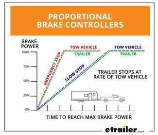
Nothing ruins a tow like jerky braking. The Redarc Tow-Pro Liberty uses a built-in 3-axis accelerometer to sense how hard you’re braking and sends matching power to your trailer brakes. If you ease onto the pedal, it eases too; stomp on it, and the trailer digs in just as firmly. It works with trailers up to 2 axles (4 brake assemblies) and supports both electric and electric-over-hydraulic systems. With proportional braking from 9V to 16V and an 18-amp continuous output rating, you get smooth stops that protect your tires and brake pads.
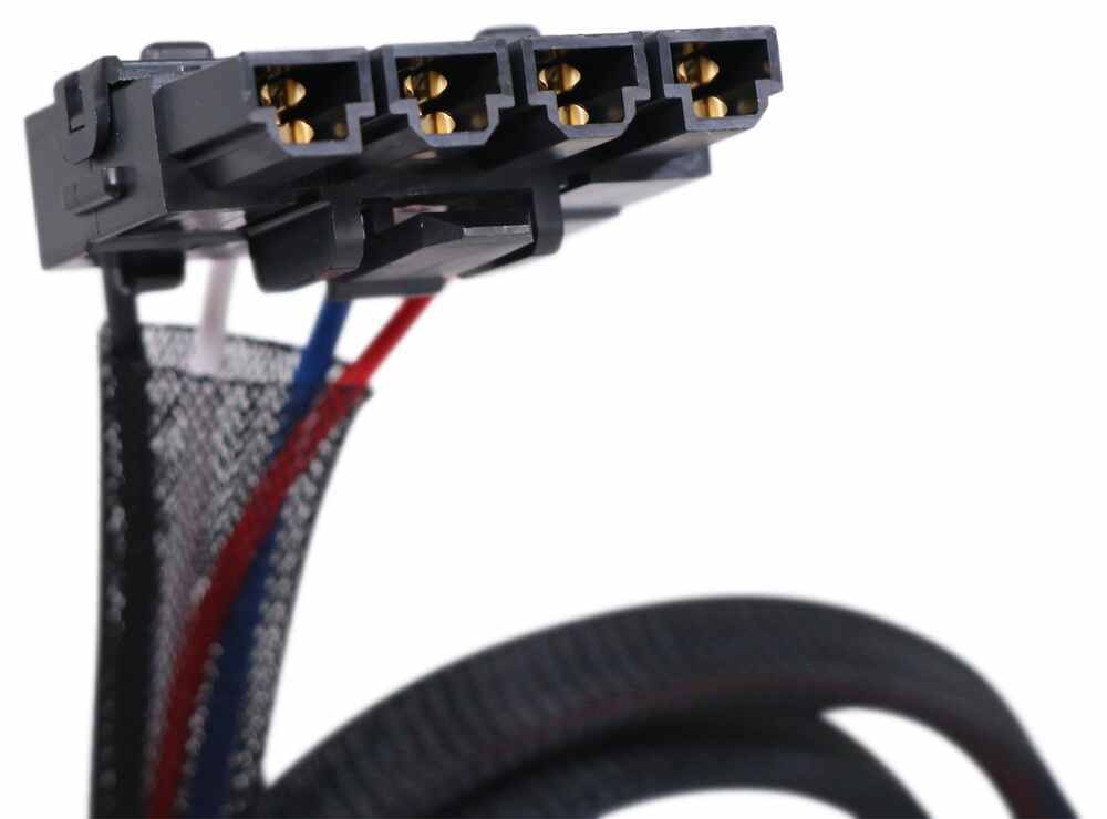
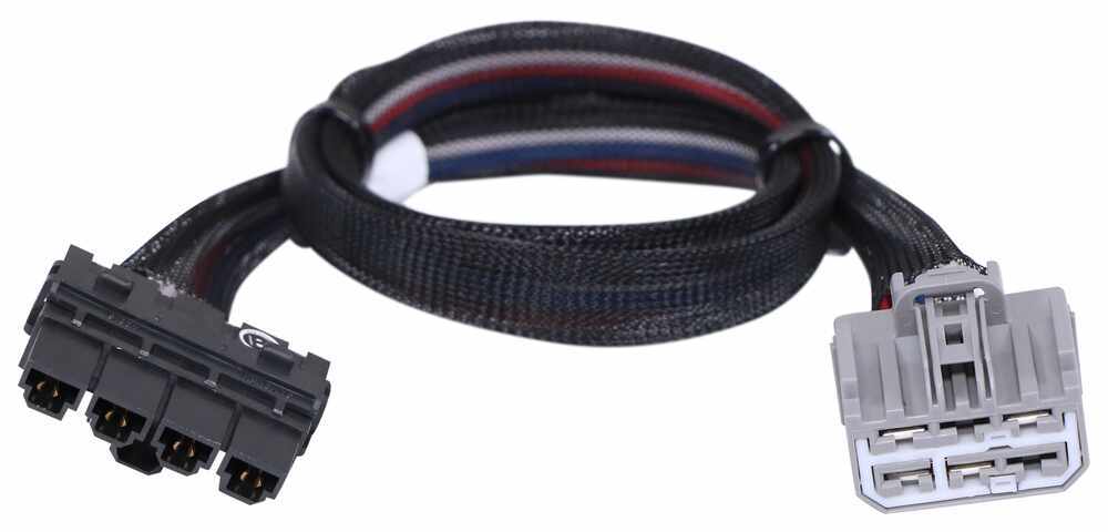
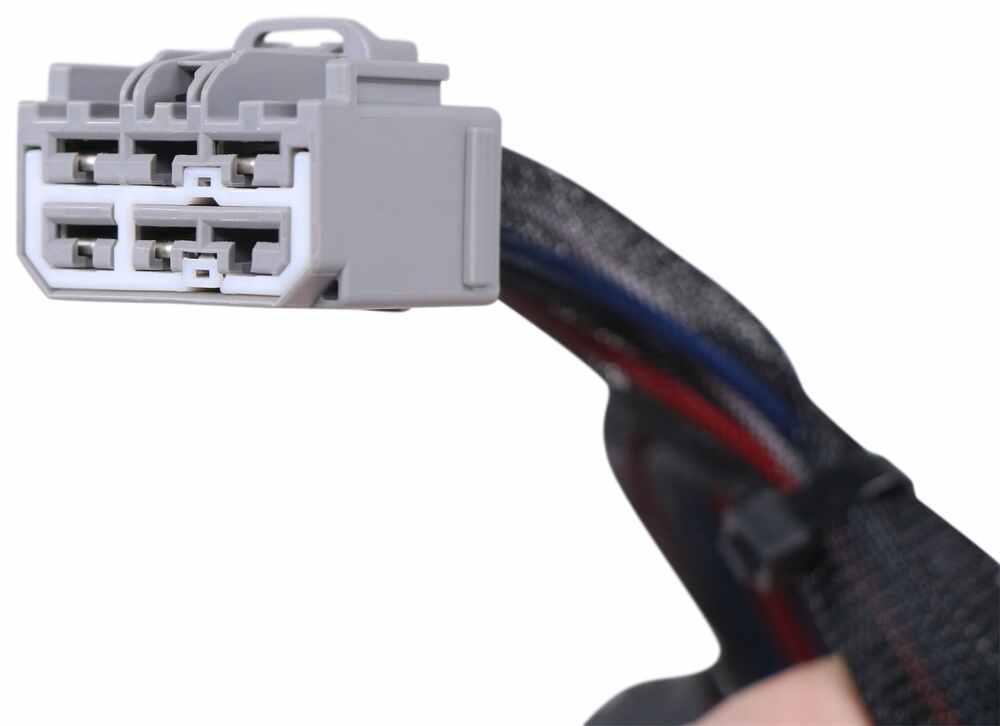
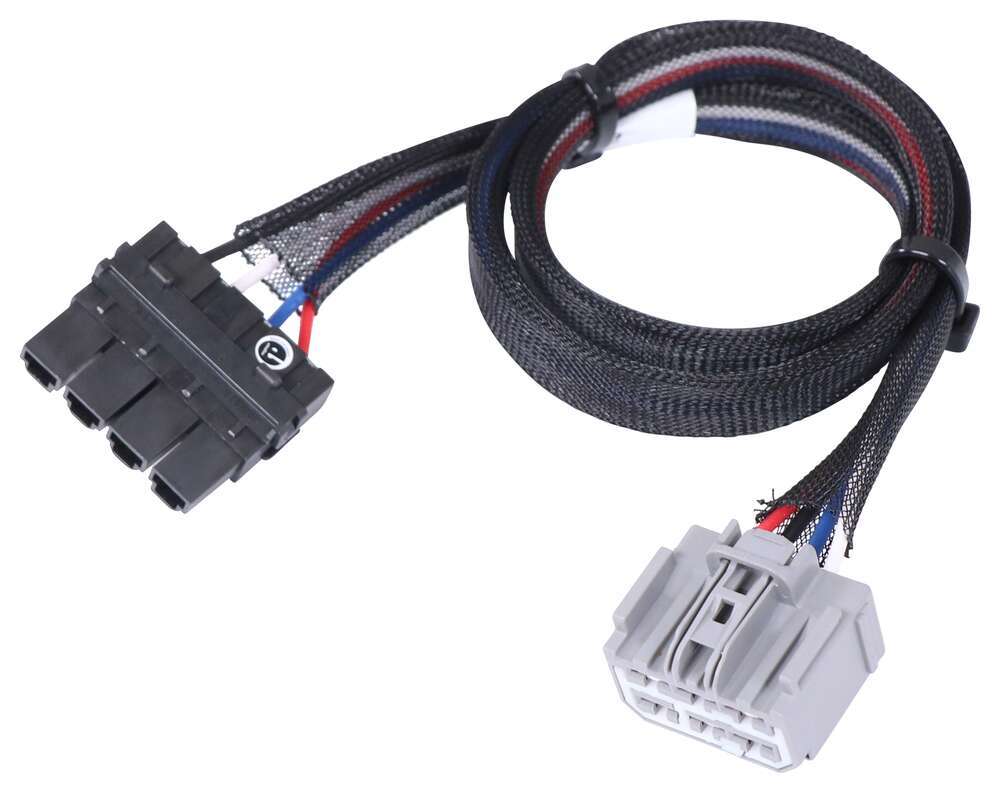
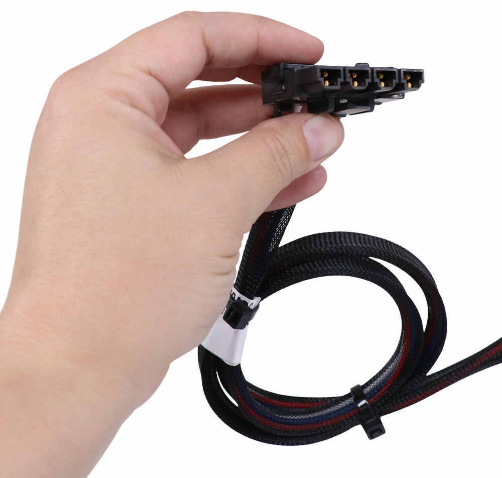
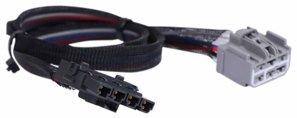
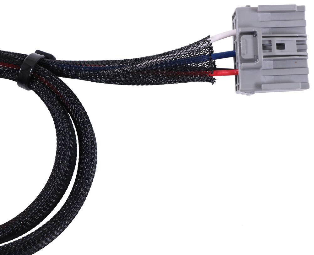
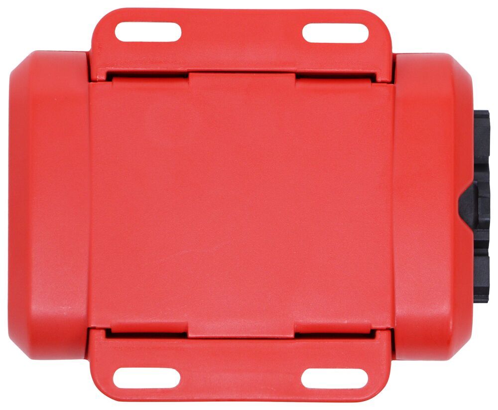
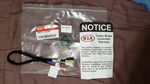
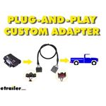
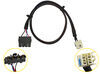
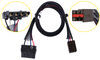
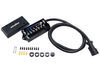
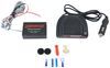
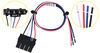
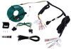
Wiring a controller doesn’t have to be a headache. The custom plug-in harness makes this one nearly foolproof—just connect the harness between the controller and your vehicle’s factory plug. The control box can mount almost anywhere within reach of the 3' cable linking it to the knob. You can secure it with screws, double-sided tape, or zip ties (not included). Once connected, calibration happens automatically as you drive, with LED lights signaling progress until the display glows solid blue.

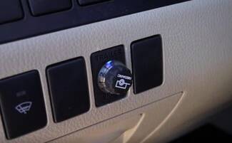
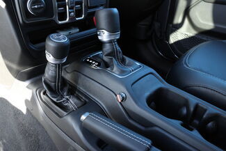
Sometimes you need to slow your trailer without touching your vehicle’s brakes—like when you feel sway or want to control downhill speed. Just press the control knob to engage manual override. It instantly activates both your trailer’s brakes and brake lights so you can steady things while staying in control.
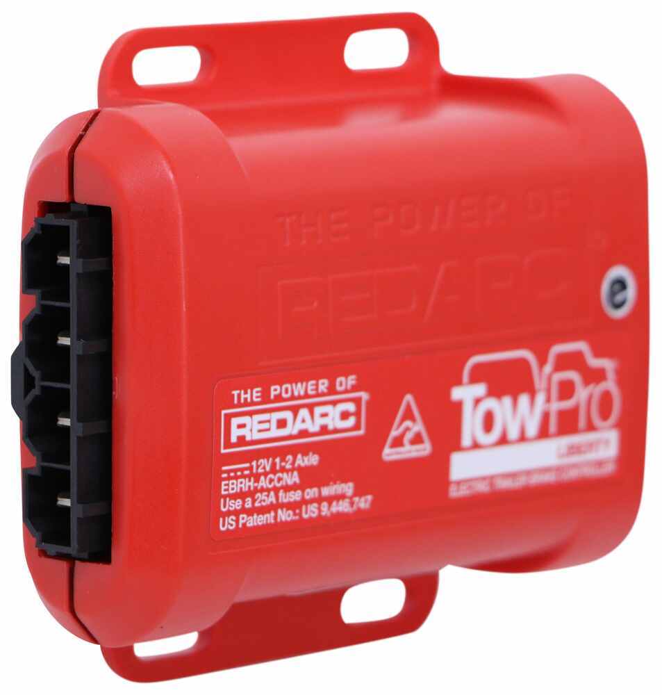
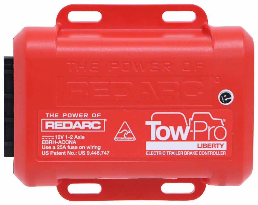
This controller meets UNECE R21 and FMVSS 201 safety standards for durability inside the cabin. With its compact housing (4" L × 3-3/8" W × 1-1/8" T), automatic calibration, and solid build quality, it’s designed for years of dependable braking performance wherever you tow.
Videos are provided as a guide only. Refer to manufacturer installation instructions and specs for complete information.
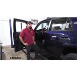
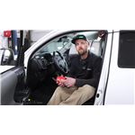
Hi there Ford owners standard 2020 Ford Explorer. We'll be taking a look at and showing you how to install REDARC's Tow-Pro Liberty brake controller. Now, the best part about the Tow-Pro Liberty is its small size and footprint that it puts here on our dash. Many of your traditional brake controllers are gonna have a box that's mounted down here in this location. And every time you get in and out, your knees come close to it, you have the potential of, you know, hitting your leg on it. Sometimes it hurts, and that could potentially damage the controller, knock it off of its brackets.
With our Tow-Pro Elite here, it's just this tiny little button in the modules hidden behind the dash. So we no longer have that big hunking box here. We still have the ability to make our adjustments just like we do at traditional controller, as well as that manual operation, so you're really not sacrificing anything going with this. I guess the only minimal sacrifice you're gonna make is that the installation is gonna be slightly more difficult, 'cause you're not just screwing it right onto the dash and plugging a wire in. We are gonna have to hide the module behind the dash, and find a mounting location for the button, but honestly, it's really not that hard.
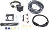
We're gonna run through this and show you some locations where you have the potential of mounting it, and we'll show you how to get this all installed. On our install today, we will be installing this on an Explorer that does not have a factory tow package. So we'll be using part number ETBC7, which is a brake controller wiring kit for vehicles that do not have the factory tow package that comes with everything you need to get this installed. If your Explorer does have a tow package, then you can just get REDARC's brake controller harness, which will save you a lot of time on your installation. We'll begin our installation here at the back of the vehicle.
There are a few things you're gonna need to have prepared before you install a brake controller. One of 'em is 4-pole flat trailer connector wiring. If you're gonna be installing it like we are here where we're using kit ETBC7, you have to have a fully functioning 4-way to make your 7-way connector work. Now if you already have a fully functioning 7-way, then you don't need to really pay attention to this part of it. But if you don't and if you don't have a 4-way, you can get a custom-fit wiring harness here from etrailer, and follow along with the video there to install your 4-way.
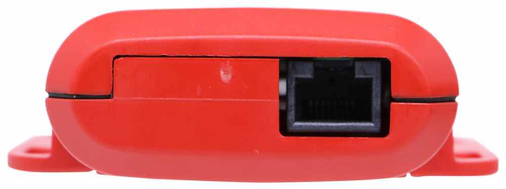
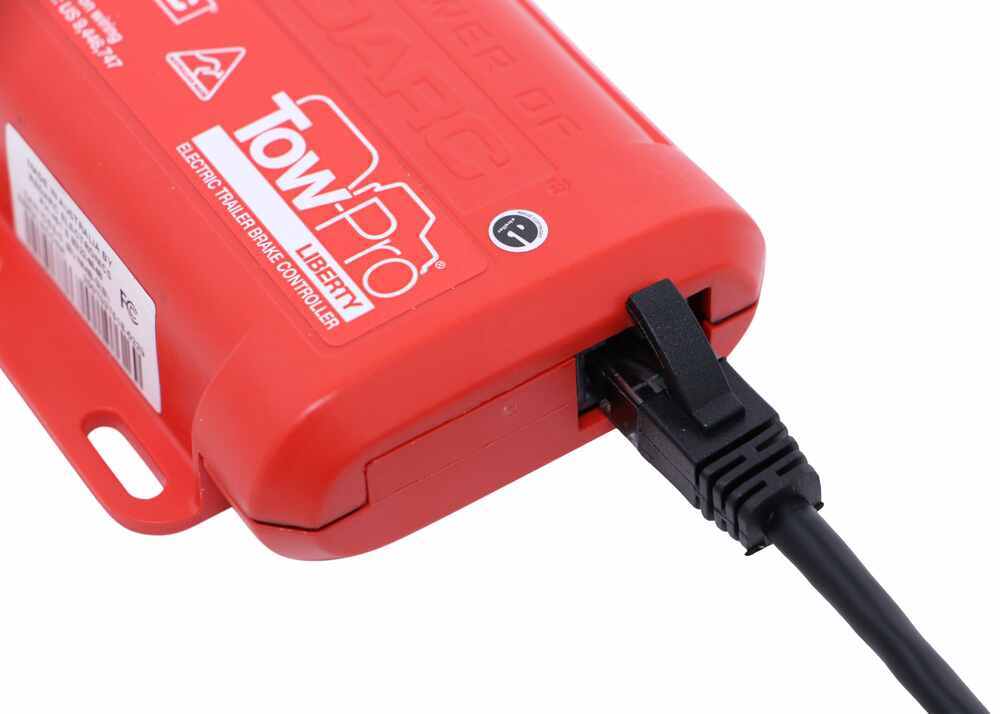
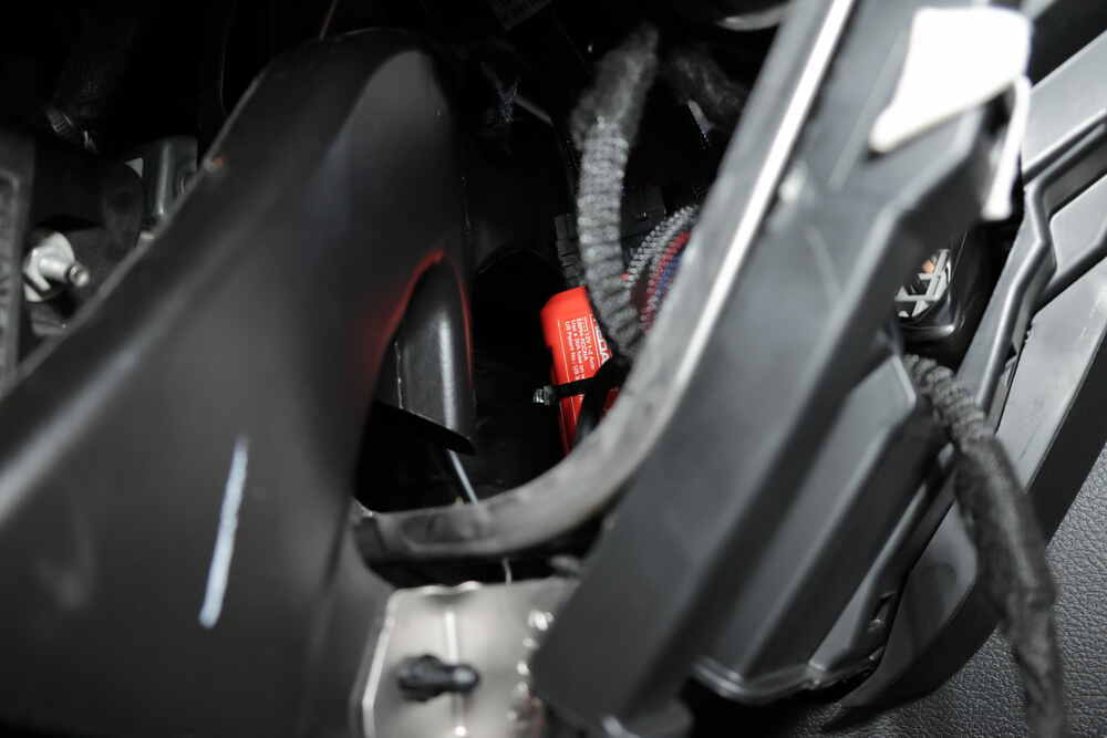
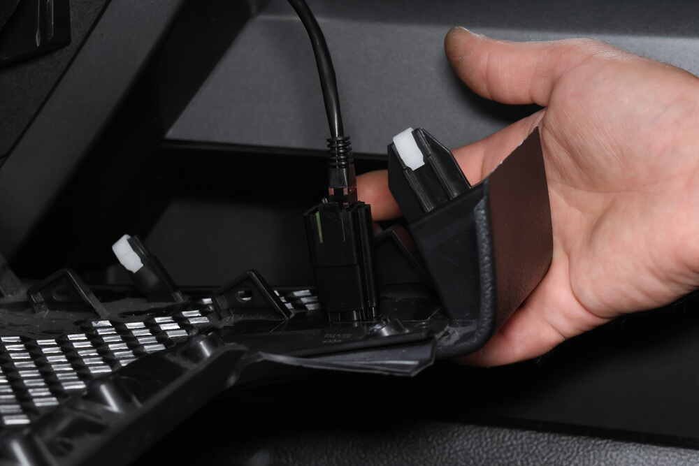
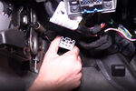
Once you have your 4-way installed, we can now upgrade it to a 7-way with this ETBC7 kit, and it also gives us all the necessary wiring components we're gonna need to install our brake controller. So we'll be using that. We're also gonna be using this bracket. In kit ETBC7, you do get a bracket for your 7-way. However, the hitch that's installed on here, the cross tube is quite high behind the fascia back here. So in order to install the bracket that comes in this kit, we would need to make our own custom brackets that would come down far enough, so we'd have a location to mount that bracket 'cause you really don't wanna mount it into a plastic paneling that's just gonna end up wearing out and potentially breaking over time. So we're using this mount here from CURT. It does not come included into your kit, but it works out really nicely here on these Explorer vehicles due to their limitations of where the cross tube is. So it just clamps right here onto the receiver tube, and gives us our mounting point for our connector there. So first thing we're gonna do is now get it mounted up. So we're gonna go ahead and slide our wiring through the opening. The little slit at the bottom's a little bit too small to slide all this wire through. Once you've got it slid through there, we're gonna use the hardware that comes with the ETBC7 kit and the connector to install it. Got that right here. We're gonna be using the black hardware. So each one has a nut flat washer and lock washer. Those are all gonna go on the back side. So line your connector up with the holes in your bracket, go ahead and slide your bolt through. And then on the opposite side, we're gonna be placing our flat washer followed by our lock washer, and then we're gonna put our nut in place following that. And let's get that loosely installed, and then we can just work our way around a bracket, installing the same hardware in each hole. And now we can go back and snug 'em down. And with these guys, you can use a wrench on the backside, but honestly, most of the time you can just hold it with your fingers and get it plenty snug doing it like that. And we're just using a Phillip screwdriver here on the other side. And I'll mount up the 4-pole connector. On the bracket that comes included with your ETBC7, there'll be a little notch on the side, this would simply slide into it. For the one that we're gonna be using here, there's a small clamp that it comes with, so we'll slide it. It's got a little groove here on the side. We'll put the groove over that. It kind of pushes on there. It's kind of similar to how the bracket that comes with the ETBC7, it's just the notches more inset. We'll then gonna use the clamp that comes with the CURT bracket. We're gonna put the small carriage bolts through the bracket and then this guy here will just slide in place right like that. And then we can put our nut on the other side and just loosely install it. And we're not gonna be tightening these very tight, 'cause we just need to hold the wiring connector here is really all our goal is. And they're really small, so they are kind of difficult to work with. There we go. We got it started in one, and then we'll flip it up and start the other one. And we'll go back and just snug them up just enough to hold the bracket securely, the connector securely. We really don't wanna tighten these very much, 'cause we can damage our connector in there. And I'm just gonna kind of work myself, work it back and forth, tightening that one just a little bit. Then we'll move up to the top one, and we're probably gonna have to find an alternate method here to get in there. Maybe you just have to use a hand ratchet maybe with a small extension to get that top one. So now we've got our connector all mounted up. We can start hooking things up. So right here, we've got the 4-pole that's on our 7-way that just takes the connector and plugs it into the existing 4-way connector that you've got on the lights on your vehicle. So we're just plugging in our vehicle's 4-way connector into the connector on the 7-way. Now we've got four more circuits here that we need to concern ourselves with. We're actually not gonna be using the yellow one. That's going to be for a reverse light, and we're not gonna be hooking that one up today, but we are gonna be hooking up what we need for our brake controller. So you've got a white wire here, which is our ground. It already has a ring terminal on it. I've already checked it. This is just not gonna reach a rounding point, so we are gonna have to extend this wire to make it long enough. And we've got our black and our blue wire. The black is gonna be our power feed for our 7-way, for the charge line, our auxiliary power circuit, and the blue is gonna be the output from the brake controller. You're gonna get some duplex wire in your kit, and we're gonna be connecting that duplex to these circuits and running them to the front so we can make our connections. I've already taken that duplex wire and ran it. And this is what the wire looks like here. You'll get plenty of it to be able to route all to the front, and we're gonna show you the path that we took to route it up there, but we need to make our connections here at the back. So we're gonna go ahead and start with these, and then we can extend this wire and get it grounded. So we can go ahead and start cutting into our duplex now. The duplex here has a gray sheathing on it and inside there's a black and a white wire. They're both a very thick gauge that we'll be able to utilize to run our circuits as necessary. We're just cutting with our razor knife down the center of it here, and that'll reveal the wires inside. We'll just trim off this excess. All right. And then we can strip back both ends of these circuits. All right. So we'll be connecting our black to our black and our white to our blue. We're not gonna use the butt connectors though that come with this component. They're regular butt connectors, and you're gonna get corrosion in there if you leave these up. So just cut those off of there. Now you won't get any heat shrink butt connectors in your kit, but I highly recommend that you replace these with heat shrinks, so that way your connections back here last more than a year. After we strip it off, we can now connect them together. So we're using these heat shrink butt connectors, you can get these here at etrailer. So we'll slide it on one side and crimp it down. And then over on the other side. since this is the black wire, we're gonna connect to the black on our connector. Give it a little bit of a twist there just help keep all the strands from deviating from where I wanted to go. There we go. And then we'll do the same thing with our white circuit now connecting it to the blue. All right. So we can grab our heat gun and shrink those down. But since we know that our white wire here for our ground is gonna be too short to reach where our we're wanting to put it. We're gonna have to extend it. So I'm gonna go ahead and cut this wire here as well, extend it, and then we can make our connections up there. And you won't get another ring terminal in your kit, so you can try and save it by using two butt connectors and just extending it in between. That's what we'll do, so that would be similar to what you guys be doing at home. So we'll cut it about here. I'm gonna strip back this in. We'll strip back this end. So we've got ourselves some extra white wire. We'll now take our butt connector, slide it on our connector end. Clip that down. We'll then grab the extension that we're gonna be using here. Slide that into place and crimp it down. On the other side of our wire, we'll use another butt connector so we can reattach the ring terminal in. All right. And that'll give us enough white wire now for our circuit to reach a location where we can attach the ground of the frame, and secure it up where it's gonna be out of the way. So we'll grab our heat gun now, and we're gonna shrink down each of these butt connectors. So now we're gonna go ahead and attach our ground. We're just gonna attach it to the bottom of the frame right at the very back, where it meets the bumper, where it goes across. We're gonna put it right there. Now, if you are having some difficulties, I'm having a pretty hard time getting the self stopper to bite. So we're gonna start with a drill bit about an eighth inch in size, and then we'll step it up from there as we need to try to get that self tapper to go in. There we go. We're gonna take our wire, slide the ring terminal on, and then we can run it back down. All right. We just wanna make sure that our circuit is secure, that you can't rotate it. And that all feels good. We're not able to rotate it. So now we can start running our wires up to the front. We'll be cleaning this up with some cable ties and stuff here in the back. Just kinda securing it all together. Probably push it up above this under panel here, and secure it all just right about that. All right. So we've gone ahead and tucked all that wiring up above the paneling there. I did poke a hole in this paneling, so I could run a cable tie through it to secure the wiring to it, 'cause we wanna keep it away from our exhaust over here. Now that duplex wire, that's gonna head towards the front. So we're gonna go ahead and just show you the path we took to get that there now. We do stay above this paneling, so we showed it. You saw it earlier when we we're making our connections, it pokes up the paneling and it runs all the way up above this paneling until we come out on the other side of our suspension here. And you can kind of see the wire a little bit right in here, where it's kind on the above the paneling. We wanna make sure we go above the suspension though, above all these moving components. We don't want our wires getting wrapped up in there, so they scale above 'em all. And then they drop down right here. We tuck it behind this paneling here at the back of the fuel tank. And then we tuck it above this paneling here, and just stay above this paneling all the way forward. There are some fasteners like here and there and there. You can use a 10 millimeter socket to remove those. So you can just fold this down a little bit, poke your wire up, and then you can put those back in. But we stay all the way up to the front of this, and that's where our duplex comes out right here. From there we just poke it up following kind of the brake lines and stuff. And our wiring's gonna come up right here. Now you do wanna be careful. Your steering shaft is right there, so we poked it, made sure we poked it underneath this wiring and stuff here, so that way it stays closer to the frame away from those moving components. We then round it up, and just cable tie it right here to this ground. Now from this point, we do need to strip back the rest of the duplex wire. So anything that's left from this point on, get rid of all that duplex, 'cause we need to separate our wires out and route them appropriately. After you get rid of that duplex, we can see here, we've got our two wires, you got the black coming out of it and the white. The black we send off to the other side, goes over there, and it's going to eventually attach to a circuit breaker, and that's this circuit right here that we ran over. We then mounted a circuit breaker right here, and we mounted our other circuit breaker right there. This is the 40 amp and that's the 30 amp. You could also use a 20 in place of the 30. You'll get both of those in your kit. We're just using the heavier one to make sure the customer has the most power. So I'd recommend the 30 anyway. So those just run in with our self-tapping screws that come in the kit. We use a quarter inch socket to get those mounted up. So this is the wire that's coming right out of the duplex. We're gonna hook this to the 40 amped circuit breaker on the silver stud. So just go ahead. And after you've cut it to lengths, strip the end and crimp on one of these small ring terminals that comes in your kit. We can then slide that onto the silver stud of our 40 amp breaker. and just run that down, and we'll secure it with a 3/8 socket. All right. Now, after you cut the excess off your black wire, we're gonna use the rest of that black wire to go inside to power our brake controller. So we went ahead and took that wire and added a ring terminal to one end. We're gonna attach that to the silver stud of the smaller breaker, our 30 ampere. I'll just slide our ring terminal on there, reinstall the nut, and we'll secure it down as well. Now the circuit breakers we got here, the bronze side, both of these will actually route into our battery, which is located right there to the positive side, to get power. We're not gonna do that just yet. That's gonna be pretty much the last step that we do, 'cause we don't want to have any live circuits while we're working on 'em. So we're not gonna connect 'em to the battery there till the end, but we will need a path to get 'em in there. So that we drill the hole right here. This was when the 4-pole wiring was installed. We're gonna use that same hole to route our wires in over there. We'll now head over to the opposite side of the vehicle again. We did drill a hole over there, and that hole we drilled right here next to where our wires routed up. So through this hole, we're gonna pass the white wire that's in our duplex wire. And then after we had cut the excess black wire off and hooked it to our smaller circuit breaker, it's gonna come back this direction and poke through that hole, so we can go inside to connect to our brake controller. Now there is a cover right here, just pops right off. There's tabs there, there, and there, and just pull it up. One on the other side, same thing, for your battery cover. But one on this side, if we look straight down from this corner here, it's pretty hard to see with a camera due to the angle, but with your eyes you could probably see it fairly well, there's a grommet, pretty big down there. It's about that big. And towards the top of the grommet, there's a small little nipple that pokes out, and that little nipple looks exactly like this, we cut it off. Just cut the end of that off, and that'll give you a point where you can pass your wire inside. Now, after you cut this side off, the other side of the grommet does have a small piece of rubber that seals it. We just took a screwdriver and poked that, so that way our wires are able to poke through. After we did that, in order to get our wiring inside, it's actually pretty difficult to just take these wires and poke 'em through that grommet even though you got a hole there now. The wires just like tend to flex up like this and curl up, and it just makes it very difficult to get 'em to actually pass through. So we're using a piece of airline tubing, but if you're doing this at home, you might have a metal coat hanger, something like that works really well that you can poke through the grommet and then pull up and then you can do some electrical tape to tape your wires through. And then we'll just pull this fish wire, and that'll bring it through our grommet on the other side. I've also found that when you tape those, it works out really well if you put some silicone on the end of it before you pull it through. And also make sure you tape all the way up to the end of your wires and a little bit past it. And we're just gonna put a little dab on there. All right, so now we're inside the vehicle. This is the driver's side here. This is your hood release lever there for opening the hood. If we follow that back, our grommet is pretty much right here, just above where your kind of footrest thing is, maybe a little bit closer to the side paneling there as we go find the grommet. And we already poked our fish wire through, so we're just pulling it back now. All right. So when we checked back up above, one of the wires had wrapped around something, so that's why it stopped. That's why if you get real stiff like that when you're pulling, just stop 'cause you might break something on the other side or you might even pull the wires outta your fish wire here and then you gotta kind of start all over again. So now we've got 'em pulled inside. We'll just remove our fish wire, and then we're gonna pull through all the slack from our wiring here. There's a good chance we'll be using some of this white wire for other purposes as well, 'cause we're just about out of the black wire in our kit. But the white wire is the same gauge, so we can still utilize that. And you're gonna have a lot more white wire here than you're black wire. All right, so we can see all this excess white, and then that's all the black that we've got. So what we've got in here now is we've got our power circuit, this black wire for our brake controller, and the white wire here, this is the output from the brake controller that goes back to the connector. We only need two more circuits for a brake controller, and that's a ground which we can source from right in here in the cab. And we need our brake input signal, which we'll get right from the factory brake switch, which is gonna be located up there. All right, and also while we're down here into the dash, we need to tap into the brake switch on our vehicle. That way when the brake is pressed, it sends an output to our brake controller, so that with the controller knows that you're pressing the brake so no stats send that output out. The brake connector is, you see your DLC right here, if you just go straight back behind the DLC, you'll find the connector for your stoplight switch located right there. So we went ahead and just disconnected it. Just press the release tab right there, and you can pull it out. I did cut off a little bit of the sheathing. It's wrapped in like this cloth tape, so I just made a little cut there to expose some of the wires. The wire in here that we need to concern ourself with is the violet with the white stripe. So I'm separating that one out. There's our violet and white stripe. We're gonna tap into it using a quick splice. We'll get some in your kit. I did change it from the quick splice though, that comes in the kit, which is a blue quick splice. We're using a red one. Red was designed for smaller gauge wires, and the blue may work, but it's a little bit, it's a little bit on the small, on large size, so sometimes it may not penetrate all the way through the wire because of the gap. So just slide your quick splice on there. We're actually gonna slide it on the other way, 'cause there's only an open end on one side for your additional circuit that you add in. So we'll take it and slide in our extra wire here into the open end onto the end that you can't push all the way through. So we've got that pushed in there. Then we'll take our other one here. I mean, it's fine if we go this direction. It's just probably be a little cleaner looking if we go this way, so we'll do that. But it's important to get your wires lined up. Okay, everything looks lined up in there now. After you've got everything lined up in the grooves, simply take a pair of pliers and squeeze the center metal tab down in place. And there we go. We've now connected an extension here. We're just using some red wire as an extension. It doesn't come into your kit. We're just using a small piece. You can directly connect the connector for your brake controller to it, but it's just easier to work with if you extend it down. So we can plug it back in, and now we can work with this wire that's hanging down. All right, we got that plugged back in. Looking pretty good here. So this is the length of wire we've got for our black and our red. They're pretty close, so we might as well take our white wire here and trim it off at a similar distance. And then we can use this extra white wire that we've got here for our ground circuit when we go to add that in. So we can start wiring in our connector now. Here's the connector for our REDARC brake controller. Now with our Tow-Pro Liberty, it actually does not come included with it, so you have to purchase this separately. I'm not sure why they do that, 'cause you have to have the connector for it to operate, but you have to purchase this separately. And we're just gonna connect them up. And for the most part, we're gonna be doing pretty much color for color, but there is gonna be some minor deviations from that. They are pre-stripped, so you can pull those ends off. That one wasn't stripped all that well, but there we go. So we've got all these exposed. We're gonna go ahead and strip back these three wires here. All right. And now we can make our connections here. So we'll start with the black wire. That's our main power wire for our brake controller. So go ahead and slide it into a butt connector. You can use regular ones here since we're inside the vehicle. Go ahead and crimp that down. And on the other side, slide in the black wire from your brake controller harness. All right, so that's our main power done. Next we're gonna do the brake output, which is the blue wire, and they're all labeled here on the sticker too. So we got that one. That's gonna connect to our white wire so. And this is the white wire that's running all the way back to the 7-way connector. And that connects to the blue wire, our brake controller harness. Now we'll hook up our red wire, which is the signal from our vehicle that the brake being pressed. So that'll connect to the red wire. We just connect it over there. So we'll match those up. And here on the other side, slide that in and we can get that crimp down. All right, so all we got left now is our ground circuit. Gonna go ahead and. We're actually just gonna leave this alone for now, 'cause we may need to extend it to reach a ground, but we may not need to extend it, you know, if we don't need to extend it. We'll assess that once we determine the location that we're gonna be installing our module. So that's gonna be our next step now is figuring out where we're gonna mount our module in here, so we can get that mounted up, get it connected, and then we'll determine where the best place to put our ground is. All right, so we decided that the best location to mount our module is actually gonna be right here just behind the DLC on this little paneling. Looks like our zip tie is gonna line up there very nice. So I'm gonna go ahead and pull this down real quick, because we know it's gonna fit there, but after we put it there, it's actually gonna be fairly difficult to get to some of the connector ends and stuff. So we wanna be able to plug those in now that we can get to it and then we can mount it up. So we're gonna take out our little harness here. This will allow us to be able to mount up our button. We're gonna save the curved end for the button side, and we're planning on putting that somewhere, probably over here in this cover. We'll probably just mount it right under the cover, 'cause this paneling is way too thick for our button to mount into. I guess we could potentially put it off to the side here a little bit, but there is some components back there. This isn't too bad of a spot though right here, so we may consider this in this spot, but we're probably gonna stick with the paneling. But no matter how you look at it, we need to have this plugged in and route it up to that location. So I'm gonna kind of start routing it there now. Let's see my module's gonna slide in from this direction. So we've got that there. This is going to plug into the ethernet side, so we'll plug it in there now, and then we can get our module up here and set it in place. There we go. Our other end here. Here we go. And then yeah, we'll make sure we hide all this stuff back. So now we'll secure it in place. We're just gonna use some cable ties to do so. Now we can push that around the module. So it comes out the other side here, and we can then secure it on the other side. Well then repeat this for the other side to get two cable ties on it. I'm gonna leave that one a little loose till I get the other one fed in, and then I can snug them both down. I do recommend leaving it loose, so you can kind of maneuver it around and get things to line up the way that you need to. Now both these holes that are here on the back of the paneling, I did have to drill those. I just use the quarter inch a bit. I just kind of held the module up there until I saw where they lined up, and then just drill them out. And then the module was long enough where this bit kind of hung out over the end, so we didn't need to drill out the opposite side. All right, that's looking all pretty good. We do still have the ground we gotta hook up. No big deal. And we gotta get our button mounted up. We're gonna get the button mounted up next, and then we'll come back to the ground, 'cause we can extend that and do all kinds of different things with it as necessary, to get it where we're gonna go. And honestly, I think we might go to this stud right back here sticking out of the firewall. That'll be a pretty decent place for us to get ground. We just need to make sure we route our cabling in a way that avoids our operation of our brake pedal there. So let's hit the switch mounted up first though. So we pulled that panel off of there. It just simply pulls out of there. There's our paneling. You can see there, it would just kind of pull out. So we're gonna try to mount it in here. You need to just double check a couple of things though before we mount it in there, and one of those is depth. That's the biggest hurdle you're gonna have when installing this brake controller, 'cause you can usually find a place for that module fairly easily 'cause you can put it pretty much wherever you want. But our button needs to be in a location that's fairly close to where we're gonna be sitting in the captain seat there so we can operate it and use the manual slide, and everything else we put on normal brake controller. So this is in pretty good reach right here. But we need to see if this is here, what kind of depth do we got So we know that this button's basically gonna be sitting like that. We are really close on depths there 'cause of this connector, so we may actually end up having to put it a little bit lower than we wanted to. Originally we wanted to put it here above just to make it a little bit closer and higher. But after assessing the depth, it's may not be possible in that location. So let's just see. I don't think it's gonna fit just due to that. The depth is huge, 'cause I'm barely, I'm probably gotta get off clearance for the button to fit, but we still have that 90 degree cable that has to plug in the backside, and I don't believe we've got the clearance for that. So we are gonna have to go a little bit lower than we wanted to. We might be able to put it next to the button, next to the handle there. We don't have the depth there either, so it's gonna have to go just below the hand where the mount is, there. The other option would've been potentially there. Let's see if we get the button in there. Yeah, we're not gonna have the depths in this location either 'cause this guy is pretty deep. It extends back over an inch, probably an inch and a half, maybe even close to two inches there, so you really gotta make sure you got that room. So we're just gonna have to drop it down some more. You know, we didn't want to, but in order for everything to fit, this is just how it's gonna have to go. So now we've determined where we're gonna mount that. We're gonna go ahead and get it mounted up. We'll drill out our location here, and then mount it right below the opening here. And we can go do that on our work bench since this paneling comes off. So now we need to drill out for our switch here. Here's our nut. This is actually the diameter we need to drill it to, 'cause the nut, that collar there, will pass into the plastic there to thread onto there, and that's a 10 millimeter diameter. Now you probably don't have metric bits at home, 3/8 is ever so slightly smaller than 10 millimeters, so we're gonna go right up from that to a 25/64, which would be just a hair larger than a 10 millimeter, which will work out nice for us. We're gonna drill it. Try to get it right here about this location. Here we go. We get that cleaned up some. Hit it from the other side, clean it up. We can take our razor knife in there and clean that up a little bit better as well. Another thing I do with my razor knife is I just kind of scrape it on the surface to take out some of those raised bars there, right near where our hole was. So that way our component here can sit more flush. Now we do got another hole we have to drill though. If we look at our switch, there's a tiny little piece of plastic there that is for our LED light, and that has to pass through. And we're actually gonna use our nut. And this is just a little collar, but if you look at the collar, it's got a hole on it where that LED lines up with. So we're just gonna slide that in there. That fits so that's good. That's one of the things we wanted to verify is that our hole's big enough. And we'll turn that collar till it's pretty much up right there. And then we'll just use this as a template. I'll probably just take a punch, and just mark like a little center punch or something, and mark that, and then I'll drill out that hole as well. And then we're just gonna use our small eight inch bit here just to drill that out. All right, so we got everything drilled out. Slide your switch in the back lining up your light on top. Slide your collar in place. Put your nut on there and then start tightening it down. We're using the 12 millimeter socket, and I'm just gonna use it in my hand here, 'cause we don't wanna over tighten this. So I'm just snugging it up. That feels like that's probably pretty good. It does rotate just a little bit, so that means we probably go a little bit more snug. And if you need to, you can brush out a tool, but I will tell you these are fairly fragile, so just be careful with them. All right, that feels more solid. All right. And once you get it tightened down, you'll wanna make sure that the switch is solid, so we can't rotate it. Also check that your button can be pressed, and we can press it. So we can go ahead and put our other button on now. Turn this fully counterclockwise, and then we're gonna take the zero and line that up with the hole right there. Double check, make sure you can press. And that seems exactly what we're looking for right there. So we'll just plug our wire into the backside of our panel here. Take the excess. Just poke that in there. I would recommend just leaving it just poked in here like this rather than cable tying it. 'Cause if you need to get to your fuses or anything, it'd be nice to have this extra length of wire to just let this panel kind of chill on the floor without hanging by the wire like that. And there we go. It did snap back into place. We had the clearance we needed to mount it here. It would've been nice to put it up there, but unfortunately just the location of connectors and stuff in the fuse box that are sticking out further prevented us from being able to do that. But this should work out pretty nice right here. It's a little bit lower than we'd like, but it is still reachable from the driver's seat and still visible. So now we're gonna go ahead and remove this nut. This is straight behind the brake pedal. I'm gonna zip that off of there. That's where we're going to. That's where we're gonna mount our ground wire. So we can go ahead and hook up our ground now. Our white wires already stripped, so now we're gonna take one of the ring terminals in our kit here. Slide your white wire in the ring terminal, and this is the small white wire off of the brake controller harness. Get that crimped down. That'll simply just slide back over the stud, and then we'll reinstall the nut. And I'm gonna turn the wire towards the outside, just try to keep it away from our pedal even more. So now at this point, we're gonna take these wires here. We're gonna secure 'em up underneath here, keep everything out of the way. And then we'll head back underneath the hood where we can get our unit hooked up directly to the battery. All right, so we've run out of the black wire that comes in our kit, but we still have some white wire that's left over, and we can use this for the last little connections we need to make. We're just gonna be going from the circuit breakers to the positive post on the battery over there. So go ahead and take your excess white and cut it in half. I do have one side that's a couple inches longer than the other, just 'cause of the difference between where those breaker sit. So we're gonna cut this in half now. And we're gonna take the half that we had cut, poke it through the hole here that we had made. That'll head over towards the battery. And we can trim off excess and stuff like that if we need to. And now we've got our two that we need for this side. So we'll hook up this side first. So go ahead and strip back each end here, and this is gonna get a small ring terminal just like the other side of our circuit breaker has there. Okay Now we can attach those to the copper toast on our breakers. All right, get that slid there. Reinstall the nut. We'll do the same thing with this one. And then we'll snug those down with our 3/8 socket. The other end of our wires, they're gonna go to the battery here. We're just gonna get these appropriately length and trimmed, something like out like that, and we'll trim off this extra. We'll strip those back. And then each one of these is going to get one of the larger ring terminals that come in your kit All right, now we can connect those to our battery here. We're just gonna tuck 'em outta the way for a moment. Lift up on our battery cover there, and we'll grab a 10 millimeter socket to remove the nuts, so we can attach it to the battery. We're gonna take both of our circuits here, and wind them up on that positive stud, and then we'll go back in here and snug them down. All right, so now that we've got everything all hooked up, if you come into your button here and press your button, you should see it pulse blue. And there's our blue pulse. It fades in and it fades out. That is the indication that you currently do not have a trailer connected. So we are gonna plug in our test box to simulate a trailer, so that way we can get some feedback from it. But once we plug in a trailer, it's gonna be flashing at us between blue and green, letting us know that it's not calibrated. So we're gonna go ahead and plug in our trailer test box. Get outside on our test course so we can get it calibrated, and we'll show you that procedure there. So we're now outside, and you can see here we've got our tester plugged in and it's flashing between green and blue with it primarily being green. As it gets calibrated, as long as you've got a trailer hooked in or some kind of test box that simulates a trailer, you'll get this feedback. As you drive the vehicle to calibrate it, all you need to do is drive in a straight line and then press the brake pedal. And this will help it learn its position in the vehicle, so it knows what orientation the inertia sensor is inside the box. You'll wanna get timed at 15 miles an hour and then press the break, and try and do it in a straight line as possible. Turns will take it longer, and it can take a potentially 20 plus break presses for it to calibrate. We're gonna do that here with you so you'll see it, but as you do this, it will slowly change to having more blue on time and less green on time as it calibrates. And eventually it'll be solid blue, letting us know that it's fully calibrated. So let's go ahead and just start our calibration process here. We are now solid blue. It is no longer flashing, so everything's working properly. And that'll do it for our look at RERARC's Tow-Pro Liberty trailer brake controller on our 2020 Ford Explorer..
Customer Satisfaction Score:
91% were satisfied with this product
9% of customers were not satisfied
Ratings & Reviews
Works perfectly. Fits in very small space. Mounted on left side and just below instrument display panel in my Honda Ridgeline. Easily visible from normal driver position. Video describing installation was extremely helpful, even though I picked a different installation position.
After much research I opted for this Redarc brake controller, the ability to tuck away the main box for cleaner appearance and incorporate the contoller switch to a factory lnstall look. The longest process of install was simply deciding where best to mount box and control switch to personal liking.
After a couple short trips to allow the unit to calibrate per our trailer, we were on the road for the season of camping. A year later and hooking up for a first outing, we notice the unit does a quick recalibration, wasn’t expected, so for this reason only I give four star. Aside from that it works beautifully and responsively to braking controls to our RV unit.
SUPER EASY to install in a 2021 Frontier. The controller box can be easily screwed/ziptied to the under dash structure in a couple places, and the adjustment control fit nicely in a blank plug in that was in the dash. The unit plugs right in to the Nissan brake controller.
It works well with a 5000 lb trailer I pull. I use a load distribution hitch and didn't realize at first that the '5' setting was using too much trailer brake. For my setup, 3.5 to 4 is perfect. It works well, and there's not a clunky controller box to bang your knees on. You'll like it!
Brake controller is working great. Looks like a factory install & it didn't take me long at all to put into my 2017 Honda Ridgeline!
This brake controller is the best I’ve used so far. It’s compact, comes with the correct vehicle wire harness splice and has been 100% reliable. Thank you!
I’ve found other brake controllers are either unreliable or too bulky. Job well done Redarc!! The safety trailer loads is of utmost importance.
2012 Jeep Grand Cherokee Overland (5.7 Hemi w/Tow pkg)
This review includes the following items: Item #RED69FR - Wiring Harness, 30A Breaker kit and Item # ETBC7 Installation Kit for Trailer Brake Controller - 7-Way RV and 4-Way Flat and Item #RED24FR Controller. I wanted to be sure I had everything. A local place Custom Coach on Pulaski Hwy, Baltimore did a fantastic job on the install, Sorry I can't remember the techs name. I have a 2018 Kia Sorento SX V6, AWD with 4 pin Tow Pkg. car rated for 5k/500# load. Trailer is a 2022 Palomino Real Lite RL-186. I've logged 2 trips so far 1 to NYS mostly highway and to Cass, West Virginia area. The controller adapted quickly, I went to a '5' to a '4' setting even in the mountains it was smooth no jerking. The one picture shows installation ubder the dash totally out of the way. It works great!
I was surprised how nice this brake controller is - clean install with the unit up under the dash. I installed the knob in one of the 'blanks' in the dash for a really clean look. No banging knees on older-style controllers under the dash. Thanks!
Working well through one season. Hoping for many more.
The hardest part was getting the zip ties tightened around the module without completely removing the trim under the steering wheel. I chose near the shifter for my location so it’s easy to reach but still out of the way.
The controller and dash knob are solid and nicely crafted. Both are made to be easy to install. The dash knob works great and is simple and easy to use. The manual is well written, and has detailed and very useful information. Be sure to get the REDARC Tow-Pro Harness (TPH-025), too, which is needed to complete the hookup of the controller.
Mounting the brake controller up and out of the way under the dash of my 2023 Tacoma required some thought. I chose to fabricate a bracket from a piece of 3/4" aluminum angle (bolted to the underside of the dash) and anchored the brake controller to it with zip-ties.
I love the separate controller and knob. The knob fit into a factory blank and the end result is factor clear. We picked up of 7x16 cargo trailer yesterday and the controller worked perfectly.
With the vehicle specific harness the install was very straight forward.
Highly recommended
The connector works. We had a connector for our Ford Explorer and there was a plug for the brake controller that came when we bought an GMC Acadia. Thinking the four wires would be the same for both, I connected according to colors. This caused the cruise control to not work in the Acadia. Determined that the brake controller was the problem, we ordered this new connector. Looking at the colors, three of the four wires went to a different color connection. It would be nice if there had been a diagram showing the wire colors for each vehicle and we would not have needed to buy another connector.
i have ordered 2 of these in the last 2 years and both times the kit was missing parts, last one i ordered the knob was missing and this last order the nut to hold the dial in place was not in the box. the product is good, but replacement pieces are not easy to find, fortunetly i had to order a complete dial kit for the one i ordered last year and i saved the rest of the parts.....
Expedited shipping was super fast with no problems. I installed the unit myself and it was fairly simple. I recommend getting the exact fitting wire harness (huge time saver) and I’d recommend getting and exact fit knock out to install the dial in. (Another big time saver). I drilled a hole in my own blank or knock out thingy and I’m pleased with it but it took a little time. I’ve got a 2010 Honda Pilot. Funny thing, after rushing to install the brake controller, our trailer had to go in for repairs before we even completed the transaction. It will be another month before I actually use the brake controller.
Etrailer is great. Service is outstanding even the return policy. My go to for trailer needs
On the Promaster when you take the BCM cover and upper dash cubby hole piece out there is a spot right above the BCM. Since the Redarc can be mounted any direction I simply added two 4mm Rivnuts to the bracket and bolted the controller in with stainless hardware (Bolt, washer, lock washer). The rest of the dash is kind of hard to find a spot, as I wanted it reachable with my right hand as I drive with my left typically. The lower instrument panel knee bolster comes down with a few screws and the inner dash piece has a hole from the factory that is perfect for the switch wiring. I used a unibit drill and a small square file to make the hole for the switch. The 90 degree cat cable is nice as it sticks through the inner hole and holds itself in place so it doesn't fall out into the bakc of the dash during assembly of the switch and there is enough room in the rear to not impede anything factory. I used a tap from O'Reillys's to tap into the brake wire suggested by the Mopar trailer wiring install guide. Typically I'd solder it, but it looks way better than a typical scotchlock connector, which I would not use under any circumstances. Ill chck its tightness in a few months and see how it holds. Used the factory wiring harness runs to run to the battery box under the floor. Used proper friction tape and braided wiring loom (O'Reilly's find) for a factory look. Seems to work ok, but need a trailer with brakes now.
This controller works amazingly well, considering the ease of installation, especially with the vehicle-specific wiring harness. I made several trips between Missouri and Colorado last year, loaded and unloaded, and a small twist of the dial compensated for the weight differences and braking requirements.
I didn't realize when I bought a new Frontier truck that I could no longer use traditional underdash brake controllers like I had for past 40 years. This meant that this Redarc was one of only a few brake controllers that I could use.
Mounting it was a bit tricky and the supplied instructions weren't good. Fortunately others before me had figured it out and posted better step by step instructions with pictures.
The brake controller itself works very well and provides the best and smoothest braking control I've ever experienced with my twin axle camper on multiple trips this last summer including one trip of over 1,000 miles around the UP of MI and northern WI.
The break controller works great...no problems. I've since sold the single axle trailer and purchased two more, one single axle new and one double axle used. I plan on stripping the cargo trailer and replacing the breaks and anything else that needs it for the suspension, creating a type of mini-home or tiny home on it. Thanks for reaching out. I will use your services for this new build. Thank you and keep up the good work!
Being new to towing a larger trailer requires research. After doing a lot of it, both through user reviews and manufacturer websites, we landed on the Rearc Liberty Brake Controller for our Tacoma. We have just over 1000 miles towing with this unit. It has performed extremely well. Towing for us includes city, highway, mountains, and even off-road to access our mountain home. Installation was straight forward and the ability to install the controller in virtually any position is an added bonus. I was able to install the dash knob in a blank panel giving the Tacoma a factory appearance, and controller located under drivers seat. I installed this unit on a non tow package Tacoma, so wiring was a bit intimidating at first. But using etrailer’s web site as a reference had everything operational in a couple afternoons. Great product so far and we look for years of use. Highly recommend.
I purchased the Redarc Liberty brake controller because I couldn’t find a place to mount my Tekonsha where I wouldn’t bash a knee or shin on it or cover an airbag.
So far, I’m very happy with the Redarc Liberty brake controller; although, I haven’t used it for towing yet, and I’m not sure it is operating properly. Apparently, I should have blue lights while it is learning which way the control unit is oriented but I don’t have blue lights.
Anyway, let me share information on the installation. I purchased the wiring harness for my vehicle, which I highly recommend as it was same cost as the universal harness, and a big time saver. I did not buy the blank switch panel for the switch installation as another reviewer stated he was able to modify the original switch blank. Big mistake, I highly recommend buying the appropriate switch panel for your vehicle. My Toyota blank switch panel was excessively complicated so I had to saw and melt a pile of plastic (see the picture) out of it without damaging the visible portion or the clips which hold it in.
Finding a suitable location to secure the controller up under the dash is a challenge with modern cars. After removing two pieces of plastic trim, I did manage to pull the panel below the steering column far enough out to complete the install. The unit it does look good. Very clean.
We’ll be towing the big trailer next week so I hope it works.
The Redarc Liberty was exactly what I wanted for my ‘20 Ridgeline. I ordered the custom pigtail and mounted everything behind the dash panel on the left side of the steering wheel. There was a blank switch cover available on the dash panel and I cut away the webbing on the back side of it (very soft plastic, Swiss Army knife) which allowed the control switch to fit right in, between the retaining clips of the blank. The drill bit sizes indicated in the instructions were not big enough for the control knob and plastic bezel so I just increased the bit sizes until the holes were big enough. Honda provided a pigtail with bare ends; I didn’t want to crimp any wires. Honda also said to put their provided fuse in slot 3 in the under hood aux fuse box; the fuse was the wrong type and there was already a 20a fuse in the appropriate slot. My Honda service tech advised Honda usually includes the wrong style of fuse and also usually installs the right one anyway. Go figure. I finished the install the night bf I picked up my new TT; took about 3 hours. It wasn't difficult but I’m pretty OCD. The most work involved routing the wires so as to avoid pinching or bending them too severely. I set the control on 5, tested it with the trailer hooked up in the sales lot and bumped it up to 6. I never felt the trailer on braking at all on the way home. Very smooth and I like the fact that it looks like a factory install. I couldn’t be happier with this controller. E-trailer’s video for the install was a great help, although I mounted the control box in a slightly different spot. This is my second purchase of towing accessories from E-trailer and I am pleased with the service and pricing both times.
Its simple and fits in the dash like it should be there. It controls the trailer as it should. it only lights up when the trailer is connected so you don't see any annoying light during normal driving. I would recommend, it has worked for me. installed in a 2016 Jeep Grand Cherokee
Installed it on my 2022 Subaru Outback Wilderness. Ordered this without the harness so had to order that separately. I think the RED52VR is what I should have ordered to include the harness. Did not like the access and the very small wire gauge on the brake pedal the instructions said to tap into so when running the wire from the 7 pin kit ETBC7 from the back of the car I ran a 3rd wire which I tapped into the brake signal going to the factory 4 pin control box in the spare tire well. I ran the wires up underside the driver side and up through the floor by the drive door rather than into the engine bay. Found a neat location to mount the controller and ground wire. Installed the control switch after drilling and dremelling the blank as shown in the great video etrailer has. Unit calibrated and worked just as advertised. Been on short test run. Need a longer trip to experiment with the brake level setting.
Info for this part was:
At etrailer we provide the best information available about the products we sell. We take the quality of our information seriously so that you can get the right part the first time.


Bill

8/7/2025
It is working.