
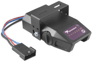
Tekonsha Voyager Trailer Brake Controller w/ Custom Harness - 1 to 4 Axles - Proportional


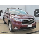
To see if this custom-fit item will work for you please tell us what vehicle you'll use it with.


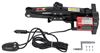
This proportional brake controller is designed to keep towing simple. Includes an LED braking indicator, a slide-bar manual override, and a knob to adjust braking power. Mounts easily within a 90-degree vertical range.
Features:
Specs:
Once the brake controller is installed, you can use the knob on the right side of the unit to adjust the gain (also known as output). Gain lets you set the maximum amount of power that will be applied to your trailer's brakes. You want to set it as high as you can without locking up the brakes. Typically, this setting is only readjusted when you experience changing road conditions or if you switch over from a heavy, loaded trailer to a much lighter, empty trailer, or vice versa.
You can fine-tune the gain by adjusting the sensitivity of the internal sensor using the knob on the left side. This controls the aggressiveness of your trailer's braking, meaning how quickly the brakes reach the maximum braking level. You can adjust this when you're towing heavy loads and you need more umph to bring your trailer to a stop. Your tow vehicle doesn't need that much power to brake in time, but your heavy trailer does. A high sensitivity level will get the braking power to your trailer brakes faster and with more intensity so that it doesn't push your tow vehicle forward.
LED Indicator
Keeping with its simple design, the Voyager will not overwhelm you with information. An LED indicator on the top of the unit lights up green to show that your trailer is securely connected to your tow vehicle. The LED indicator will change to red when the brakes on your trailer are activated.
During installation and setup, this light is also used to ensure that the Voyager will be able to function correctly. Proper leveling of the internal sensor is crucial to the operation of this brake controller. When the sensor is level, the LED will change to a shade of orange.
The Voyager is designed to be mounted in your cab at a vertical angle that is between -20 degrees and 70 degrees. The brake controller needs to be horizontally level and parallel to the direction of travel in order to function properly.
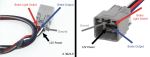
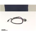
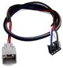
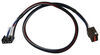
To connect the Voyager, just plug the included harness into your vehicle. The other end plugs into the controller - no hardwiring required.
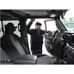
Once the controller is mounted and connected, you must level the internal sensor. First, set the overall power to the maximum using the knob on the side of the controller. Then, while pressing the tow vehicle's brake pedal, adjust the level knob on the other side of the brake controller (this is the same knob that is used to fine-tune the power output) until the LED monitor is a shade of orange.
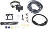
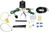
Note: If you don't already have a 7-way plug at the back of your vehicle, take a look at our exclusive 7- and 4-way brake controller installation kit (ETBC7 - sold separately).
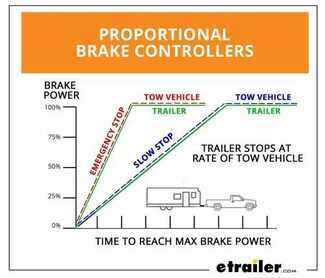
The Tekonsha Voyager brake controller comes equipped with proportional braking to give you the best towing experience. Proportional braking means that your trailer brakes mimic your tow vehicle's brakes. If you slam on the brakes in your vehicle, your trailer brakes will activate with the same intensity; if you brake lightly, your trailer brakes lightly too. The trailer's braking is in proportion to your vehicle's braking. This saves wear and tear on the tires and the brakes on both your vehicle and trailer.
The Voyager uses a pendulum system to sense how your vehicle is braking so it can send the right amount of braking power to your trailer. It measures the inertia of your tow vehicle and activates the trailer's brakes to slow at the same rate. The result is uniform braking across your towing setup. No push-pull action - just smooth, proportional braking every time.
 Alternate Instructions
California residents: click here
Videos are provided as a guide only. Refer to manufacturer installation instructions and specs for complete information.
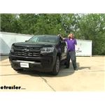
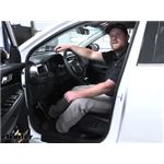
Hi there, Colorado owners. Then your 2022 Chevrolet Colorado we're gonna be taking a look at and showing you how to install Tekonsha's Voyager proportional Brake Controller. This is a proportional brake controller so the inertia sensor inside will detect vehicle movement. So if you ever slam on the brake show your body like kind of slams forward the inertia sensor detects that, and it knows that it's your vehicle is slowing down based on that. And it uses that along with your adjustment controls to give you the best breaking performance at the back. This is a very simple brake controller beyond the adjustment for a level and the output control.
On the other side, you just have your manual slide which can be used for if your trailer starts to sway or anything you kind of hit the manual slide to apply the brakes on your trailer and to help straighten you back out and get rid of that sway. And that's kind of it. This brake controller is just very simple gives you that fully proportional break output. And it does work with trailers up to four axles. We'll begin our installation here on the driver's side.
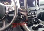
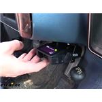
We're right down here at the kick panel. There's the parking brake pedal. I'm gonna go ahead and push it down just to help make things a little bit easier to see. And this panel here we're gonna be removing to remove the panel. You're just simply gonna pull up on it.
So your fingers should be able to grip underneath of it here. And kind of at this middle point here we're gonna pull up and we're gonna be working our way towards the back of the panel, pulling up on it. There we go. Once you get the back released and get towards the front here, you're gonna kind of pivot it like this and pull away from the wall here. You got a clip right there and that'll pop out of there.
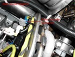
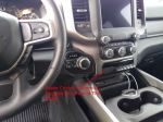
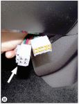
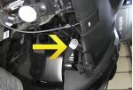
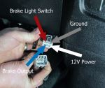
And then we can just set this panel aside behind our panel. You're gonna find your factory break controller wiring and it's just taped right here cut the tape and that'll expose our wires there. We've got four wires here and this will hook into our brake controller. We're gonna use a harness. It has four wires on it as well. So everything will just match right up to what we've got right here. So we can make our connections. Now for demonstration purposes today we're not gonna be fully mounting it. We're gonna use some hook fasteners to secure it and we're not gonna be opening up the little hardware pack that it comes with. So that way we can repackage that. So we're gonna strip back each one of these wires and hook them up. I like to do it one at a time just because the red wire here, is your hot wire. So once you strip it back, that wire's live there. So I kinda like to get that hooked up right away to prevent it being stripped and potentially shorting up. So we're gonna go ahead and just take our start with our red wire here. It has a green Stripe on it. That's our main power wire. So we're just gonna strip it back. You may wanna trim a little bit off cause it's got those little ends on it there. So we'll probably trim a little bit of this off and then strip it, just to make it easier to strip with that material that it had on there. So give it a little twist makes it slide into the butt connectors more easily. We'll slide our butt connector on there and then we'll attach our wire to it. We can now hook this up to the appropriate wire here on our new harness. That's gonna be the black wire on our harness to power up our module, our brake controller. So we'll slide that in the other end of our butt connector and make our connection. So now that we've got that connected there we're just going to repeat that process to connect the rest of our wires. We'll be hooking the blue wire in our harness to the blue wire here on the vehicle. That's the output from the brake controller. So that'll send it down this wire to the back. The uh, white wire here on our harness is ground. And that'll actually hook to the black wire here on our vehicle. That'll be our ground. And then the red wire here, on our harness is for the brake signal input to the brake controller. So that's coming from your brake pedal here. So it lets the brake controller know when you're pressing the brake pedal and that'll connect to the white wire with the small blue Stripe on it there. So I'm gonna strip each one of these back and then make those connections and then you'll see those here. All right. So now that we've got all of our connections made here I'm gonna reinstall this panel and kind of tuck my wiring out the top of it when I reinstall it and we're gonna be mounting our brake controller roughly in this location here, that way it's kind of out of the way our wiring will reach it easily position it just off to the left so we can still access our hood release switch. And that is now fully reinstalled. We still have access to our wiring there to be able to Mount our controller. Now, typically when you mount your controller you're gonna screw the bracket straight into the dash. But again, for demonstration purposes we're gonna be using some hook and loop fasteners just to stick it there. So that way we don't mess up the dash here. That is not really how you wanna leave your brake controller installed 'cause this is an inertia based controller. So it means to detect vehicle movement. So it is important you screw it in place. Now, after we've got it mounted up we'll simply just plug our controller in that'll plug right into that harness. Now this harness doesn't, did not come included with the Voyager controller here but you can buy it kitted that way here at e trailer, to ensure that you get it with your brake controller. But if you just need the brake controller maybe you've already got one of these harnesses, you can buy just the brake controller by itself without the harness kited with it. After you plug in your brake controller you can kind of hide the wiring behind the dash there. And at that point you can see it's powered up. I plugged in the tester here to simulate a trailer. And if we hit our manual slide you should see the gauges activating on our tester there. And we can see we've got output. It's actually pulling ampage and it was operating both or it was operating our brake lights as well. You can see you get a real time display on top of the amount of output that you're putting towards your trailer's brakes based on the L E D light on top. Green being basically like no output going to yellow for a minimal amount, transitioning up to red for maximum. And as you slide the manual slide, you can kind of control how much of that output you're putting up. So once you verify it's working we do need to level this system. It's this very quick calibration. So that way the inertia sensor knows the angle that you've tilted it at to adjust that with your trailer connected and everything hooked up you wanna make sure the knob here on the right side is set to the maximum. So turn it fully clockwise to maximum put it to maximum output. And then the adjustment knob you see here on the left this is your level adjustment. We're gonna turn that one fully counterclockwise. So that's gonna be kind of turning it this direction. We're then gonna press the brake pedal. Our output is red. Red is gonna be the most aggressive setting. We wanna turn our level knob clockwise. Now bringing it back towards us. Once it turns orange, that's kind of your typical setting. That's usually where you're gonna wanna set that level adjustment at to get the typical output. But if for whatever reason you need a little bit more aggressive breaking you can tilt it. You can turn it a little more counterclockwise to get to that darker orange or red to be more aggressive. But you kind of wanna hover around that area of orange between that orange and like lighter red like right when you're getting into the red that'll get you at a nice setting for the inertia sensor to operate properly. And then we can use our maximum control knob here. This is the output from our brake controller. Just properly set that for your trailer. The heavier your trailer is, the higher you're likely gonna need this set. The smaller your trailer is and you can might be able to back it off and turn it down. You'll again, when you adjust that knob when you hit the brakes that will affect the L E D. So I've got, it turned fairly low and you can see it's a very light shade of orange but as I increase that, it becomes more aggressive. So just find the setting that works best for your truck and trailer combination there. And then you're good to go..


Do you have a question about this Trailer Brake Controller?
Info for this part was:
At etrailer we provide the best information available about the products we sell. We take the quality of our information seriously so that you can get the right part the first time. Let us know if anything is missing or if you have any questions.


Thank you! Your comment has been submitted successfully. You should be able to view your question/comment here within a few days.
Error submitting comment. Please try again momentarily.