
To see if this custom-fit item will work for you please tell us what vehicle you'll use it with.


This is one of our favorite brake controllers, with flawless braking and a tiny dash knob that looks like it came straight from the factory. Its unique off-roading mode helps you handle rough conditions, so get out there and get towing.
Features:
Specs:
The off-road mode is a unique feature of the Redarc Tow-Pro Elite. In this mode, the brake controller will apply your trailer's brakes with a preset amount of power, independent of what your tow vehicle is doing. This is ideal for off-roading or challenging conditions. Set the power low if you're towing through sand or mud so that the trailer doesn't stop with too much force and act as an anchor. If navigating a steep descent, set the power to a higher level to ensure that the trailer doesn't push against the tow vehicle.
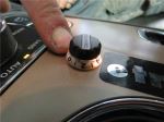
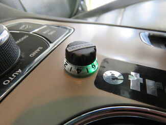
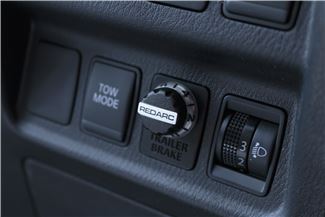
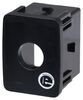
To activate the off-road mode, rotate the knob counterclockwise and apply your vehicle's brakes. Push down on the knob twice (2 times within 1 second) and release the brakes. The knob will turn green to let you know that the mode has been activated.
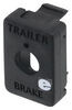
Use the knob to set the braking output -- the maximum amount of power that will be applied to your trailer's brakes. To get more power output, rotate the knob clockwise toward 10. To decrease the power output, rotate it counterclockwise toward 0.
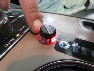
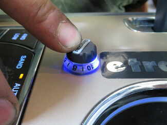
When you apply the tow vehicle's brakes, the knob will change from blue to red to signal that the trailer brakes are being activated. The higher the braking power output, the deeper the red that you will see.
To engage manual override, simply press the control knob. This will activate the trailer's brakes and brake lights independent of your tow vehicle, great for stopping sway or controlling your trailer's momentum in an emergency.
When you are calibrating the brake controller for the first time, the LED lights will signal your progress.
You'll start by braking 20 times or so to let the unit learn its orientation and the direction of travel. You don't need to have a trailer connected for it to calibrate; the only difference is that the knob won't illuminate at all. If your trailer is connected, the LED light will flash green/blue as it calibrates. When the display turns solid blue, initial calibration is complete.
Once done, the unit will remain calibrated. If recalibration is required, it will happen automatically and without LED indication.
The Tow-Pro Elite has almost no mounting restrictions. It comes in 2 pieces: the main unit and the control knob. The main unit can be mounted out of sight and out of the way. You don't have to worry about dinging your knee on a bulky brake controller or interfering with your vehicle's airbags.
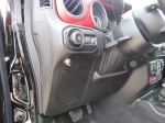
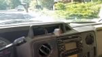
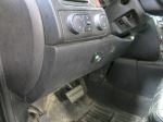
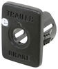
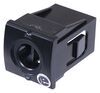
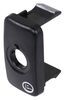
The control knob can be installed in any convenient spot that's easy for you to see and access. This can be a blank switch panel, an open spot on your center console, or wherever there's space on your dashboard. A universal mounting panel is included to ensure a clean, from-the-factory look. Custom-fit panels are available for certain vehicles as well. Before you do any drilling, be sure there's enough clearance behind the dash for the entire knob to install!
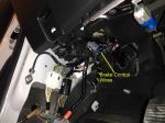
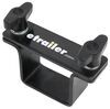
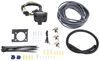
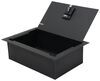
Once you've decided where you want to put the control knob, you'll need to find a good place to install the main unit. Your only restriction is the 3' cable connecting the main unit and the control knob. Securely mount the box using screws, double-sided tape, or zip-ties (not included). A mounting kit (RE67FR - sold separately) is also available for the Tow-Pro Elite. Do not attach the module to wiring or cables that can shift as you drive!
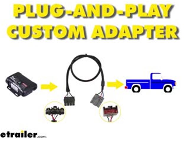
Then plug the custom-fit harness right into your vehicle and the brake controller and you're done!
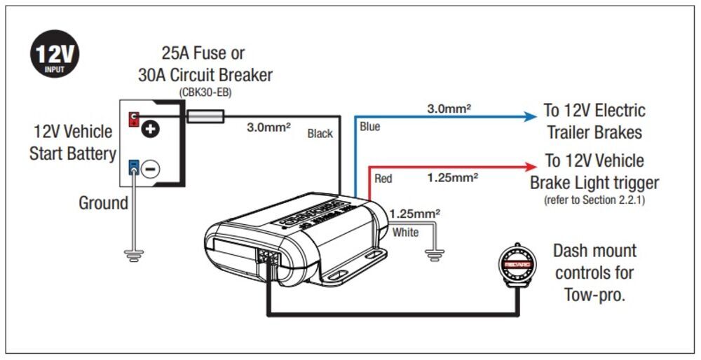
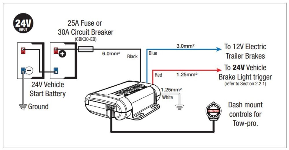
If you don't already have a 7-way plug at the back of your vehicle, take a look at our exclusive 7- and 4-way brake-control installation kit (ETBC7 - sold separately). A 30-amp circuit breaker kit (331-CBK30-EB - sold separately) may also be required for installation.
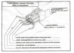
For assistance in properly wiring the Tow-Pro Elite, please refer to the diagrams below:
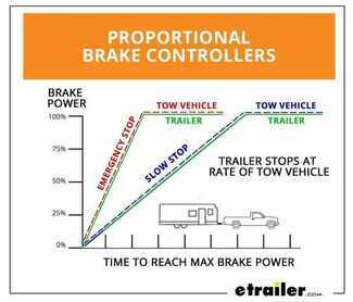
Proportional braking means that your trailer brakes mimic your tow vehicle's brakes. If you slam on the brakes in your vehicle, your trailer brakes will activate with the same intensity; if you brake lightly, your trailer brakes lightly too. The trailer's braking is in proportion to your vehicle's braking. This saves wear and tear on the tires and the brakes on both your vehicle and trailer.
The Tow-Pro Elite uses an internal 3-axis accelerometer to sense how your vehicle is braking so it can send the right amount of braking power to your trailer. It measures the inertia of your tow vehicle and activates the trailer's brakes to slow at the same rate. The result is uniform braking across your towing setup. No push-pull action - just smooth, proportional braking every time.

California residents: click here
Videos are provided as a guide only. Refer to manufacturer installation instructions and specs for complete information.
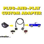
Brad Hello neighbors. It's Brad here at etrailer. And today we're taking a look at the vehicle-specific wiring harness, that will work in conjunction with the Tow-Pro Elite electric trailer brake controller. These harnesses are going to be great to work with your Tow-Pro Elite in a variety of different trucks and SUVs. Now, make sure that you get your vehicle-specific harness. You're going to want to use our fit guide on "etrailer.com", and that's going to make sure that you get the right harness, and that way your install goes nice and easy.
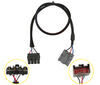
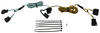
Included in the REDARC kit, you will find this plugin adapter, and this is going to have these spliced ends, and you're gonna have to tie into your brake signal, your brake output, your power output and your ground. Now, if you are pretty handy with electrical, that's awesome. That's great. You can use this. But I'm the kind of person, plug and play in OEM kind of setup or really nice factory one like this.
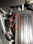
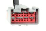
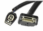
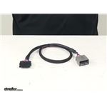
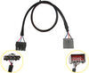
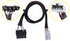
This is the vehicle-specific harness. So this ties in directly to our factory tow system, and clips right in, it's got this nice braided sheathing on it, to kind of protect the wires, and then it plugs directly into our module here. So, to save yourself a little bit of headache and time, and make the install go that much smoother, and not have to worry about loose connections, I highly recommend getting the vehicle-specific harness. So this end of the plug is specific to your vehicle. As you can tell, it looks like the factory plug, it fits in perfect, has the locking mechanism, so you aren't gonna have to worry about loose connections happening with your plug, and it's going to make install a lot easier.
And that was a look at the vehicle-specific harness for the Tow-Pro Elite electric trailer brake controller..


Do you have a question about this Trailer Brake Controller?
Info for this part was:
At etrailer we provide the best information available about the products we sell. We take the quality of our information seriously so that you can get the right part the first time. Let us know if anything is missing or if you have any questions.


Thank you! Your comment has been submitted successfully. You should be able to view your question/comment here within a few days.
Error submitting comment. Please try again momentarily.