

 Arrives before Christmas
 To see if this custom-fit item will work for you please tell us what vehicle you'll use it with.


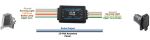
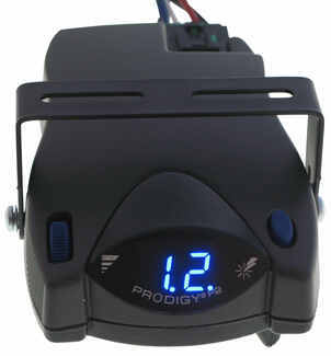
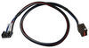
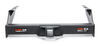
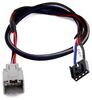
The Tekonsha P2 is a classic brake controller you know you can rely on. It's easy to install, and with the custom harness, it's plug-and-play.
Features:
Specs:
Gain is the maximum amount of power that will be applied to your trailer's brakes. How much braking output you need is determined by the weight of your trailer; a heavier trailer will need more power to bring it to a stop. You want to go as high as you can without the trailer brakes locking up.
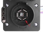
You can adjust the gain by turning the thumbwheel on the front of the controller.
The boost setting controls the aggressiveness of your trailer's braking, meaning how quickly the brakes reach the maximum braking level. If your vehicle takes too long to come to a stop, increase the setting. If it stops too abruptly, decrease the setting.
Depending on the level of boost, your trailer brakes can start at either 13 percent or 25 percent of the set gain. So instead of starting at 0, the brakes will start at 25 percent and get to 100 percent sooner. This keeps the trailer from pushing your tow vehicle forward.
Boost Levels:
| Approximate Gross Trailer Weight | Boost Level | Increase in Initial Power Output |
|---|---|---|
| Less than tow vehicle GVW | B1 | 13% |
| Equal to tow vehicle GVW | B1 or B2 | 13% or 25% |
| Up to 25% more than tow vehicle GVW | B2 or B3* | 25% |
| Up to 40% more than tow vehicle GVW | B3* | 25% |
*Both B2 and B3 offer a 25-percent boost in initial power. But the braking curve for B3 is more aggressive than that of B2. This means that, even though you will start out with the same intensity when using these boost levels, you will get an overall more aggressive braking experience with the higher level. So if you use B3, you will reach maximum braking sooner than if you use B2.
To engage the manual override, twist the rotary-style lever from right to left. This will activate the trailer's brakes and brake lights independently of your vehicle, great for stopping sway or controlling your trailer's momentum in an emergency.
The Prodigy P2 offers key safety features to prevent damage to your towing setup:
- Integrated reverse battery protection shields the brake controller and your trailer's breakaway system from shorts.
- When the P2 is not in use, it draws only 3.6 milliamps to minimize the drain on your vehicle's battery.
- Any time your vehicle and trailer are at a standstill with the brakes applied for more than 5 seconds, the hold feature will kick on and reduce power to just 25 percent. This will keep your trailer in place without your brakes overheating.
The Prodigy P2 also runs continuous diagnostics to check for problems as they come up, including:
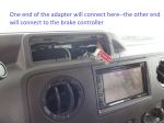
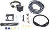
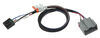
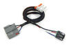
Installing the P2 is incredibly simple. You'll mount the bracket to your dashboard then mount the unit to the bracket. Plug the custom harness into your vehicle and into the unit. Done!
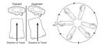
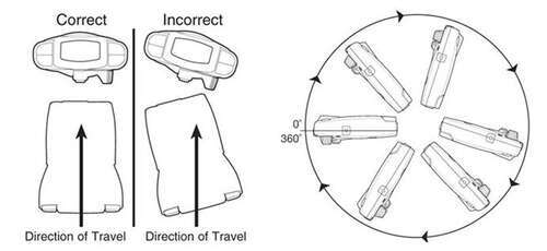
Keep in mind that the P2 must be horizontally level and parallel with the direction of travel to work correctly.
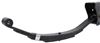
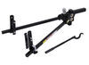
With a replacement wiring harness (sold separately) and replacement bracket (P7685 - sold separately), you can even transfer the Prodigy P2 to another vehicle.
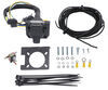
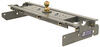
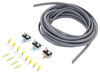
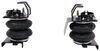
Note: If you don't already have a 7-way plug at the back of your vehicle, take a look at our exclusive 7- and 4-way brake controller installation kit (ETBC7 - sold separately).
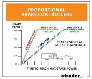
Proportional braking means that your trailer brakes mimic your tow vehicle's brakes. If you slam on the brakes, your trailer brakes will activate with the same intensity; if you brake lightly, your trailer brakes lightly too. The trailer's braking is in proportion to your vehicle's braking. This saves wear and tear on the tires and the brakes on both your vehicle and trailer.
The Prodigy P2 uses an internal inertia sensor to detect how your vehicle is braking so it can send the right amount of braking power to your trailer. It measures the inertia of your tow vehicle and activates the trailer's brakes to slow at the same rate. The result is uniform braking across your towing setup. No push-pull action - just smooth, proportional braking every time.
 Alternate Instructions
California residents: click here
Videos are provided as a guide only. Refer to manufacturer installation instructions and specs for complete information.
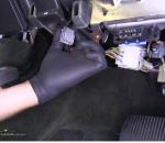
Today on our 2014 Ford Explorer, were going to be installing the Tekonsha Prodigy P2 Trailer Brake Controller, part number 90885. In addition to our brake controller, were also going to need to install the Universal Installation Kit for Trailer Brake Controllers, part number ETBC7, as well as the no-drill mounting bracket, part number 18140. Without a trailer connector when you slide the manual override here, youll get a NC showing that theres no trailer connected. Now, well go ahead and plug a trailer in. With our trailer plugged in, youll see now a C appears on the screen showing that you are connected.Now when you do the manual override, it shows you what the power output going to the electric trailer brakes is. Now, this roller knob over here on the left-hand side is what adjusts the maximum output or the output that can go back to your trailer brakes.
This little button up here on the top right is the Boost Feature button which applies how aggressive the power will come on to the trailer brakes. Now, were going to begin with the ETBC7 portion of our installation. Now, the reason why you would need an ETBC7 is if your vehicle does not have any factory prep for a trailer brake package. Thats what this kit does, and you will need to already have a 4-flat wiring harness on your vehicle.Were going to go ahead and put the bracket together here off the vehicle. Well go ahead and slide the bracket through the wires like this.
Well then going to go ahead and attach it using the hardware provided. Well go ahead and drop a screw down in. Put a locking nut on the backside. Do that at all four corners. We can then go ahead and tighten everything down.
Now, the next portion of our bracket thats going to hold our plug in place is a short no-drill bracket. That will attach something like this, so well be using the hardware that comes with the no-drill bracket to attach that to the bracket that comes with the ETBC7 kit. Put the screw in, and then well put a locknut on the underside. Go ahead and tighten down the hardware again.Now, youll see here that our vehicle does already have a 4-flat wiring connection on it. Well go ahead and move that out of the way for a little bit.
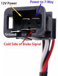
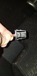
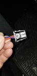
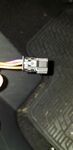
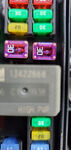
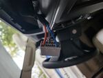
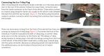
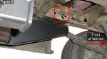
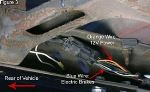
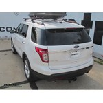
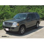
Now, well go ahead and take our bracket, and slide it up and over our hitch. Well then take the provided hose clamp. Well go through the bracket around the hitch itself, then come back in through, or well tighten down the hose clamp securing the bracket to the hitch. Well go ahead and take a pair of tinsnips, and trim off any excess hose clamp. Next, were going to go ahead and need to connect the 4-flat wiring off the back of the 7 and 4-way plug to the 4-flat wiring already installed on the vehicle.Before we do this, well add a little bit of dielectric grease which is part number 11755. Go ahead and plug the connection together now. Well then go ahead and add a zip tie to make sure that the connector stays together. Then, go ahead and trim off any excess zip tie. Next, were going to take gray duplex wire that comes in the kit. Well need to strip back a little bit of the gray covering. Well then need to strip back a little bit of wire from both the black and the white wire, and well be connecting these two wires with the black and the blue wire with the butt connector already on them that come off the back of the 7 and 4-way plug. The white wire will go to the blue wire, and the black wire will go to the black wire like that. Go ahead and crimp both down.Now, this black wire is what will go up to the positive side of the battery for your 12-volt hat in your 7-way plug, and the blue wire connected here to the white wire is the electric brake signal wire. Now, we can go ahead and tape up each of these two connections with a little electrical tape to help protect it from the elements. Now, we still have two wires that come off the backside of the plug. One of them is a white wire that has a ring terminal on it that well need to ground somewhere to the frame of the vehicle using a self-tapping screw. The other wire is a purple wire that depending on your application can be tied in with the reverse light circuit and will be used for items such as a reverse lockout or similar.Now on this case, were not going to be hooking up this purple wire, so well just tape it off for now. Now here on the backside of the plug, were going to go ahead and trim down a piece of the half-inch wire loom that comes with the kit, and well slide it on to the wire just to give it a little more protection. Well also use a little bit of electrical tape to make sure that the wire loom stays in place. Now, weve gone ahead and bunched up our extra wire. Im just going to use a little bit of tape to help keep it in place for right now, and well be using a few zip ties to help secure it off as well.Now, weve gone ahead and routed our white wire with the ring terminal on it which is our ground around the hitch and over here to where we can get a solid ground from the frame of the vehicle. Well be using a self-tapping screw to ground our ground wire. Next, well need to take our gray duplex wire. Go ahead and pull all the slack through. Were going to go ahead and take our duplex wire now, and well route it up to the front of the vehicle making sure we stay away from areas that may become hot, have moving parts, or sharp edges as all of them could easily damage the wire. Well also be using a few zip ties along the way to help secure our wire.Now, were going to take a razor knife, and were going to need to remove the gray covering from the rest of the wire as the white wire will be pulled into the cab of the vehicle, and the black wire will route up to the battery. Next, were going to need to go inside the cab of the vehicle. Now, were going to go ahead and peel back the carpet a little bit here on the driver side. Were going to need to trim out some of the plastic, so we can gain access to the firewall. Take our razor knife to do that. Now with an area of the firewall exposed, well go ahead and take a smaller bit or a pilot bit. Go ahead and drill a hole in order to route our wire through the firewall. Well go ahead and open up our hole to match the size of our grommet.Now when we drill a hole, were going to then install a snap bushing grommet which is part number SWC8057. Now, well go ahead and take our grommet, and push it down into position. Then, well need to go back underneath the vehicle and continue running our wires. I will go ahead and pull our black wire up. Next, were going to need to find a location to mount two breakers. Right in here is a good spot to do it. Were going to need to trim a little bit of this rubber back. Just go ahead and take our razor knife and trim it back some. Now, were going to go ahead and well be attaching a 40-amp breaker which is this one right here, and thats for the 12-volt power supply on our 7-way plug.Were going to be using a 20-amp breaker which is right here for the power that goes to our brake controller. I will go ahead and take our 40-amp breaker, and well be attaching it to the body right in this area. Then, well go ahead and attach our 20-amp circuit breaker. I will go ahead and trim our black wire here to length. Well go ahead and connect it here to the bottom stud or the chrome color stud on our 40-amp breaker. Go ahead and trim the wire. Strip a little wire back. Well then be attaching one of the supplied smaller ring terminals to the wire here. Well go ahead and take the nut and the washer loose. Go ahead and put the washer and the nut back on. Then, go ahead and tighten down the nut.Now, were going to make a jumper that runs from the copper side of our circuit breaker over to the positive side of the battery. Go ahead and strip some wire. Add a small ring terminal to the one side. Well go ahead and connect it to our circuit breaker, so we get the right length. Go ahead and open up the battery side. Go ahead and trim our wire to length. Strip some wire back. Go ahead then and add a larger ring terminal to the end of the wire. Crimp it down. Now, were not going to actually connect it quite yet until we finish the rest of the wiring.Now, well go ahead and take another section of the black wire. If its long enough, you can run from the 20-amp chrome or silver color stud down into the cab of the vehicle through that grommet for the power for the brake controller. If its not quite long enough, go ahead and use it to make your jumper from the copper side over to your positive side of the battery, and youll need to get an additional length of wire to go from here into the cab of the vehicle. Go ahead and strip back a little bit of the one end. Well add a small ring terminal to it. Crimp it down. Now our piece of wire is long enough, so were going to go ahead and connect it to the silver or the chrome side of our 20-amp breaker.Now, weve gone ahead and got another short piece of wire here to make our final jumper. Well connect the small ring terminal to the one end. Go ahead then and connect it here to our copper side of our 20-amp breaker. Go ahead and trim it to length. Strip a little bit of wire back, and then well add a large ring terminal to this end. Well leave these two off the positive side of the battery for now until we finish our other wiring. Well then go ahead and take this length of wire. It comes off the 20-amp circuit breaker. Well feed it down, and in through the grommet, feeding it into the cab of the vehicle.Now before we go back out from underneath the car, were going to go ahead and trim off any excess zip tie that may be left over from routing our wire to the front of the vehicle. Next, were going to need to remove a panel thats here up underneath the dash. To do that, well need to take this screw out here as well as right there. Over here in this corner, if you pull, theres a little tab that holds this corner in place. Go ahead and set this piece out for now. Now once we got the under panel removed, we we're able to find this port right here. This port actually has a brake signal off of it.We used our test-light to find out which wire is the brake signal, and we found it to be the blue wire with the orange stripe. Now, we know which wires will go to what. The blue wire with the orange stripe will go to the brake signal wire. Now next, were going to need to choose a location to mount our brake controller. Were going to go ahead and choose. We used the plastic pocket with the brake controller to mount it. Well be mounting it here on the lower portion of the dash using the two supplied screws. Now, well begin by taking our black and our white wire, and cutting them down a little bit. We dont need them quite so long. Go ahead and set that aside.Well then going to have to add a butt connector to each end, and well need to strip a little bit of wire back. Well then be connecting the blue wire off of the harness that comes with the brake controller to the white wire, so well be connecting these two together. Well be connecting the black wire with the black wire here. Now the black wire here, this is the positive or the power lead. Well then go ahead and strip a little more wire back here on our white wire. This is the ground. Well be adding a ring terminal to the white wire, so we can ground it underneath the dash here.Finally, our red wire will tie in with the blue wire with the orange stripe as this is our brake signal wire. To do that, well just use a quick-splice connector. Go ahead and take our quick-splice connector. Slide it over the blue wire with the orange stripe. Well then take our red wire, slide it into position. Go ahead and cramp everything down. We can go ahead and close the cover on it. Next, were going to go ahead and remove this nut right here. Were going to add in the white wire with the ring terminal which is the ground underneath it. Go ahead and put the nut back on, and tighten it down. Go ahead and tape up these two butt connections.Next, well go ahead and take our wires. Route it over here to the pocket. Feed it up through. Well plug it in to the backside of our brake controller. Make sure that you hear it click and lock into position. Slide our brake controller back down. Next, well go ahead and uncover the positive side of the battery. Well then going to go ahead and take both of our ring terminals that are on the end of the black wire, and trim out the center section. It will look something like that. Go ahead and take this one out as well. Then well be loosening this nut right here, and sliding both of the ring terminals underneath in line with this other existing wire. Go ahead and tighten it back down. We can put the cover back down.Next, were going to go ahead and add some sealant to seal up the area around our grommet where our wires come through the firewall. To do that, were going to be using some Loctite sealant which is part number LT37467. Now with our sealant in place, we can go ahead and take our wires, secure them using a zip tie or two. Go ahead and trim off any excess zip tie, and then we can reinstall our panel. We can then go ahead and put our two screws back in that secure the panel. That will do it for our installation of the Tekonsha Prodigy P2 Trailer Brake Controller, part number 90885 on our 2014 Ford Explorer in conjunction with our Universal Installation Kit for Trailer Brake Controllers, part number ETBC7.


Do you have a question about this Trailer Brake Controller?
Info for this part was:
At etrailer.com we provide the best information available about the products we sell. We take the quality of our information seriously so that you can get the right part the first time. Let us know if anything is missing or if you have any questions.


Thank you! Your comment has been submitted successfully. You should be able to view your question/comment here within a few days.
Error submitting comment. Please try again momentarily.