Diode Installation Instructions for a Dinghy with Separate Tail Light Wiring
Before you begin the installation ensure that your vehicle being towed has a separate system, with turn signals on a separate circuit from brake lights, often carried behind a separate lens.
- These instructions are rough guidelines of steps that need to be taken. The procedure varies from vehicle to vehicle.
- Throughout the FAQ, the vehicle being towed will be referred to as the dinghy and the vehicle doing the towing will be called the tow vehicle
Procedures
There are two acceptable ways in which a dinghy can be wired in this scenario. Below is an outline of each procedure and the end result
Option 1
- Makes the dinghy appear to have a combined system while being towed. The amber lights will not function when being towed, but will function normally when the dinghy is driven normally.
- This is accomplished by wiring the dinghy's brake light circuits to carry both the brake light and turn signal for each respective side
- This is the simpler of the two procedures
- Does not require the installation of a converter on the dinghy
- Requires tapping into 3 circuits on the dinghy
Option 2
- Tail lights on dinghy function as if they were being operated from inside the vehicle, illuminating the separate turn signals
- This is accomplished by wiring into each of the dinghy's individual lighting circuits
- This is a more difficult installation
- Requires installation of a converter to change the combined signal from the tow vehicle to separate signals for the dinghy
- Requires tapping into 4 circuits on the dinghy
Procedure for Option 1: Wiring the Dinghy like a Combined System
To Begin: Mounting, grounding and running the wire to the dinghy tail lights
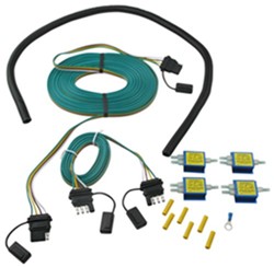
- Find a place on the front of the dinghy to mount the female-end of the 4-way connector of the wiring harness from the diode kit
- Strong bumpers can be a good connection point. If you are leaving the connector loose, ensure that it can be tied up out of the way and will not come in contact with anything hot.
- Ground the white wire with a ring terminal to a clean, metal surface somewhere on the vehicle frame
- Route the length of bonded wire along the vehicle frame to the rear of the dinghy, avoiding hot or moving parts
- If possible, run the harness down the side opposite the exhaust outlet
- Zip-tie the wire along the vehicle to secure it in place
- Cut off the excess wire of the harness, including the 4-way connector, and leave adequate length to run the wires to the respective tail lights
- Split the bonded wire, leading the yellow and brown wire to the left-hand side and the green wire to the right side of the vehicle
- Set wiring harness aside for a moment
Installation
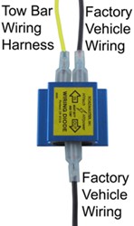
Locate the dinghy's factory running light and brake signal circuits and install a diode in-line with each. This process is outlined below. The diode installation is the same for each circuit
- Left brake and turn:
- Locate the factory left brake circuit using a circuit tester
- Sever dinghy's left brake signal wire and install a diode in-line with the circuit
- Using a spade connector, take the loose end of the factory wire coming from the front of the vehicle and attach it to one of the two prongs on the input side of the diode
- Connect the loose end of the factory wire running to the tail light to the single prong on the output side of the diode. This reestablishes the dinghy's tail light circuit
- Tie in the left-turn and brake circuit from the tow vehicle using a spade connector
- Attach the yellow (left turn and brake) wire from the wiring harness to the remaining input prong on the diode
- Tape up connections to secure them
- Right brake and turn: Repeat left-brake and turn procedure on the right side of the vehicle


- Running lights:
- Locate factory left-side running light wire on the dinghy and install diode, leaving one input prong open (temporarily hold off installing the wire from the wiring harness)
- Next, locate factory right-side running light circuit and install diode, again leaving one input prong open
- Create a jumper wire to carry the running light circuit from the left-side running light to the right-side running light
- Cut an extra length of wire that can extend from the left-side diode to the right-side diode
- Twist the loose end of the jumper wire on the left side and the brown wire from the wiring harness together and insert the twisted end into the spade connector
- Connect both wires to the remaining prong on the right running light diode
- Run the remaining loose end of jumper wire across and attach it to remaining prong on the input side of the right running light diode
Procedure for Option 2: Wiring the Dinghy as a Separate System
To Begin: Mounting and Grounding
- Acquire a length of bonded wire, preferably a 4-wire bond, that can be tied into the vehicle tail light circuits and reach to the hitch of the tow vehicle, like the wire in the Universal Hy-Power Diode Wiring Kit, part #RM-154
- Find an appropriate location at the front of the dinghy for the trailer connector that will later be added to the beginning of the harness. Start your harness from that spot.
- Ground the white wire from the harness with a ring terminal to a clean, metal surface somewhere on the vehicle frame
- Route the length of bonded wire along the vehicle frame to the tail lights of the dinghy, avoiding hot or moving parts
- If possible, run the harness down the side opposite the exhaust outlet
- Zip-tie the wire along the vehicle to secure it in place
- Set wiring harness aside for a moment
Converter Installation
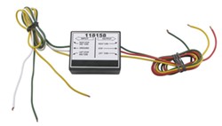
- Near the tail lights, on the left-hand side of the vehicle, find a secure mounting location for the vehicle tail light converter, like Vehicle to Vehicle Tailight converter from Tow Ready, part #118158
- Wire in the converter
- Input
- Ground the white wire coming from the converter using a ring terminal to a clean, metal surface somewhere on the vehicle frame
- Attach the green wire from the harness to the green wire on the input side of the converter
- Attach the yellow wire from the wiring harness to the yellow wire on the input side of the converter
- The brown wire from the harness does not need to pass through the converter. Set it aside for the next step
- Output
- These wires will be connected to the diodes. Follow instructions in "Diode Installation" to complete wiring
- Input

Diode Installation
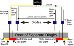
Locate the dinghy's factory running light, brake and turn signal circuits and install a diode in-line with each. This process is outlined below. The diode installation is the same for each circuit.
- Left turn:
- Locate the factory left-turn circuit using a circuit tester
- Sever dinghy's left-turn signal wire and install a diode in-line with the circuit
- Using a spade connector, take the loose end of the factory wire coming from the front of the vehicle and attach it to one of the two prongs on the input side of the diode
- Using a spade connector, connect the loose end of the factory wire running to the tail light to the single prong on the output side of the diode. This reestablishes the dinghy's left-turn circuit.
- Tie in the left-turn circuit from the tow vehicle wiring harness using a spade connector
- Attach the yellow (left-turn) wire from the converter to the remaining input prong on the diode
- Tape up connections to secure them

- Running lights:
- Locate factory left-side running light circuit and install diode, leaving one input prong open (temporarily hold off installing the wire from the wiring harness)
- Next, locate factory right-side running light circuit and install diode, again leaving one input prong open
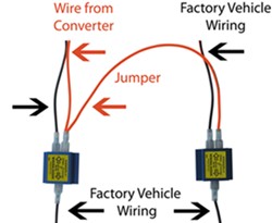
- Create a jumper wire to carry the running light circuit from the left-side running light to the right-side running light
- Cut an extra length of wire that can extend from the left-side diode to the right-side diode
- Twist the loose end of the jumper wire on the left side and the brown wire from the wiring harness together and insert the twisted end into the spade connector
- Connect both wires to the remaining prong on the right running light diode
- Locate factory right-side running light circuit and insert diode
- Run the remaining loose end of jumper wire across and attach it to remaining prong on the input side of the right running light diode
- Brake lights:
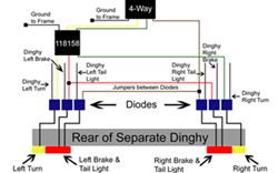
- Locate factory left-side brake light circuit and install diode, leaving one input prong open
- Locate factory right-side brake light circuit and install diode, leaving one input prong open
- Create a jumper wire to carry the brake light circuit from the left-side brake light to the right-side brake light
- Cut an extra length of wire that can extend from the left-side diode to the right-side diode
- Twist together the loose end of the jumper wire on the left side and the red wire from the converter box and insert the twisted ends into a spade connector
- Connect both wires in the spade connector to the remaining prong on the right brake light diode
- Run the loose end of jumper wire across the back of the vehicle and attach it to remaining prong on the input side of the right brake light diode
- Right turn:
- Run a length of wire from the green wire on the output side of the converter to the right-side turn signal
- Connect the green wire from the output side of the converter to the extension
- Locate the factory right-turn circuit and install diode using process outlined in the "left turn" process
- Attach the end of the extension coming from the green wire on the converter to the open input prong on the right-turn diode

Connecting the Vehicles
A wiring extension cord must be run from the tow vehicle to the dinghy to connect their two wiring systems.
- Extension cord runs from the trailer connector at the rear of the tow vehicle, over the tow bar, and to the trailer connector installed on the front of the dinghy
- There are two scenarios that could occur:
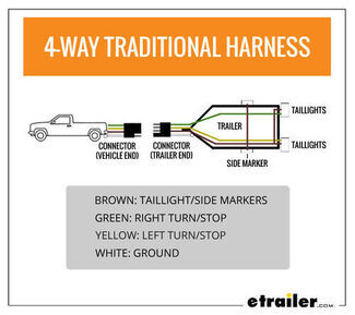
- Your RV and dinghy have corresponding trailer connectors (e.g. They both have 4-way, female connectors)
- Your RV and dinghy do not have corresponding trailer connectors (e.g. RV has a 7-way, female connector and the dinghy has a 4-way connector)
- There are two ways to make ends meet:
- Ensure that the tow vehicle and dinghy trailer connectors correspond, and purchase an extension cord that has the appropriate trailer connectors
- Example: Both your RV and dinghy have female, vehicle-end, 4-way connectors. An extension cord with two 4-way, trailer-end, male connectors can connect the two wiring systems.
- This may require replacing one or both of the existing trailer connectors on the vehicles.
- Oftentimes, this 4-way jumper cord is included in the diode wiring kit
- Find a jumper cable that has ends that correspond to each one of the vehicle connectors
- Example: Your RV has a 7-way connector, and your dinghy has a 4-way. The connector cable will need to have a trailer-end, 7-way connector on one end and a 4-way, trailer-end connector on the other.
- Ensure that the tow vehicle and dinghy trailer connectors correspond, and purchase an extension cord that has the appropriate trailer connectors
- Before connecting the vehicles, attach the jumper cord to the tow vehicle and test the plug at the other end of the jumper cord to make sure the appropriate circuits are carried on the appropriate prongs
Note: Extension cords for towing a vehicle are unique. Unlike a standard wiring adapter, both ends of the extension cord will have male, trailer end connectors. Ensure the extension cord you purchase for your setup has the appropriate trailer connectors on each end.
To see available extension cords and connectors click here
Updated by: Raymond P.
Last updated: 6/29/18
Departments
Towing
- Trailer Hitch
- Fifth Wheel
- Gooseneck
- Towing a Vehicle
- Front Hitch
- RV Hitch
- ATV Hitch
- HD Truck Hitch
- Vehicle Wiring
- Brake Controller
- Ball Mounts
- Weight Distribution
Sports and Recreation
Trailer Parts
- Utility Trailer
- Boat Trailer
- Landscape Trailer
- Enclosed Trailer
- 5th/Camper Trailer
- Car Hauler
- Horse Trailer
Vehicle
Contact & Help

What our customers are saying:
"Very helpful/friendly Customer Service. Competitive Pricing. Shipping was Fast."


