

 Arrives before Christmas
 To see if this custom-fit item will work for you please tell us what vehicle you'll use it with.


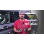
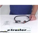
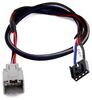
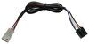
The Tekonsha P2 is a classic brake controller you know you can rely on. It's easy to install, and with the custom harness, it's plug-and-play.
Features:
Specs:
Gain is the maximum amount of power that will be applied to your trailer's brakes. How much braking output you need is determined by the weight of your trailer; a heavier trailer will need more power to bring it to a stop. You want to go as high as you can without the trailer brakes locking up.
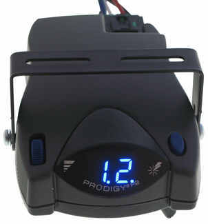
You can adjust the gain by turning the thumbwheel on the front of the controller.
The boost setting controls the aggressiveness of your trailer's braking, meaning how quickly the brakes reach the maximum braking level. If your vehicle takes too long to come to a stop, increase the setting. If it stops too abruptly, decrease the setting.
Depending on the level of boost, your trailer brakes can start at either 13 percent or 25 percent of the set gain. So instead of starting at 0, the brakes will start at 25 percent and get to 100 percent sooner. This keeps the trailer from pushing your tow vehicle forward.
Boost Levels:
| Approximate Gross Trailer Weight | Boost Level | Increase in Initial Power Output |
|---|---|---|
| Less than tow vehicle GVW | B1 | 13% |
| Equal to tow vehicle GVW | B1 or B2 | 13% or 25% |
| Up to 25% more than tow vehicle GVW | B2 or B3* | 25% |
| Up to 40% more than tow vehicle GVW | B3* | 25% |
*Both B2 and B3 offer a 25-percent boost in initial power. But the braking curve for B3 is more aggressive than that of B2. This means that, even though you will start out with the same intensity when using these boost levels, you will get an overall more aggressive braking experience with the higher level. So if you use B3, you will reach maximum braking sooner than if you use B2.
To engage the manual override, twist the rotary-style lever from right to left. This will activate the trailer's brakes and brake lights independently of your vehicle, great for stopping sway or controlling your trailer's momentum in an emergency.
The Prodigy P2 offers key safety features to prevent damage to your towing setup:
- Integrated reverse battery protection shields the brake controller and your trailer's breakaway system from shorts.
- When the P2 is not in use, it draws only 3.6 milliamps to minimize the drain on your vehicle's battery.
- Any time your vehicle and trailer are at a standstill with the brakes applied for more than 5 seconds, the hold feature will kick on and reduce power to just 25 percent. This will keep your trailer in place without your brakes overheating.
The Prodigy P2 also runs continuous diagnostics to check for problems as they come up, including:
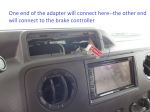
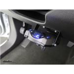
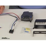
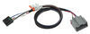
Installing the P2 is incredibly simple. You'll mount the bracket to your dashboard then mount the unit to the bracket. Plug the custom harness into your vehicle and into the unit. Done!
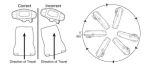
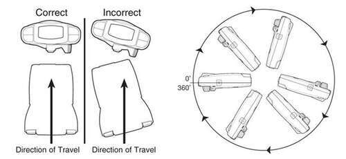
Keep in mind that the P2 must be horizontally level and parallel with the direction of travel to work correctly.
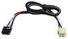
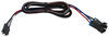
With a replacement wiring harness (sold separately) and replacement bracket (P7685 - sold separately), you can even transfer the Prodigy P2 to another vehicle.
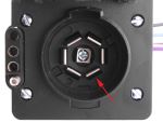
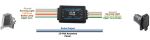
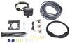
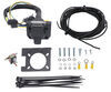
Note: If you don't already have a 7-way plug at the back of your vehicle, take a look at our exclusive 7- and 4-way brake controller installation kit (ETBC7 - sold separately).
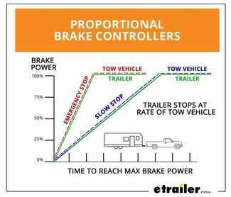
Proportional braking means that your trailer brakes mimic your tow vehicle's brakes. If you slam on the brakes, your trailer brakes will activate with the same intensity; if you brake lightly, your trailer brakes lightly too. The trailer's braking is in proportion to your vehicle's braking. This saves wear and tear on the tires and the brakes on both your vehicle and trailer.
The Prodigy P2 uses an internal inertia sensor to detect how your vehicle is braking so it can send the right amount of braking power to your trailer. It measures the inertia of your tow vehicle and activates the trailer's brakes to slow at the same rate. The result is uniform braking across your towing setup. No push-pull action - just smooth, proportional braking every time.
 Alternate Instructions
California residents: click here
Videos are provided as a guide only. Refer to manufacturer installation instructions and specs for complete information.
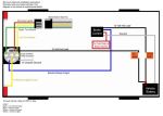
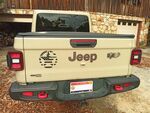
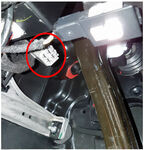
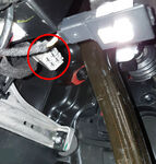
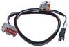
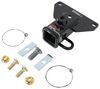
Today, on our 2004 Jeep Wrangler, well be installing the Tekonsha Prodigy P2 Brake Controller, part number 90885 in conjunction with the Etrailer Brake Controller install kit, part number ETBC7. Using the hardware and bracket provided, we can secure the 7-pole bracket to the new 7-pole connector. The 7-pole connector will have both a four flat and seven blade trailer connection points. Well that bolts and nuts provided to secure the 7-pole bracket to our new 7-pole. Now, as we have our fasteners installed finger tight, well go ahead and run them down to secure the bracket.Next, we can go ahead and take the bracket and secure it directly to the hitch-mounted bracket. Now that our 7-pole is secured to the hitch, we can start connecting our wires.
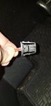
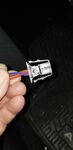
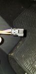
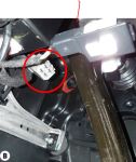
Before I connect any of my wires, I'm going to go ahead and tape up a portion of our 7-pole pigtail here just to help bundle the wires up and protect them. Using some black electrical tape, Ill go ahead and put it around the pigtail. Note, this is also inaudible 00:01:48 you can use the wire loom thats provided with the install kit. Next, well take the 4-pole plug thats already been installed under the vehicle. Bring it down to our 7-pole where we can connect the two flat-pole connectors together.
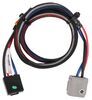
Ill go ahead and remove the cap because itll not longer be needed.Then before I make that connection, were going to use some dielectric grease between the two connection points to help prevent corrosion over time. Well be using the Edelmann Dielectric Grease, part number 11755 and then make my connection. We can take the purple wire used for trailer reverse lights. It will not be hooked up in this application so were going to go and cut it short, but its long enough that if we need to, we can go back and add to it to connect the trailer reverse lights. Next, were going to attach the gray duplex cable to our black and blue wire leads.
The gray duplex cable has two wires inside. Were going to go and expose them by cutting back a couple of inches of the sheathing. Be careful not to cut the wiring underneath when you split the sheathing. You can peel it back, just cut it off out of the way. Then well go ahead and strip back the two wires.The black wire will connect color-to-color, black-to-black and this will provide the 12-volt hot lead directly to our 7-pole connector.
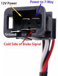
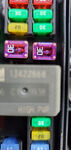
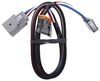
The other lead will be the blue wire from the pigtail and the white wire from our duplex cable and this will provide power to our trailer braking. Now, once Ive made my connection points back here, I'm going to go ahead and finish wrapping up my electrical lead with some black electrical tape. This will help keep our connections clean from dirt, dust, debris and moisture. Ill get my wire out of the way before I tape it up. Im just going to simply route it up and over the frame, going towards the front of the vehicle and ultimately, up to the engine compartment. I will include the white wire with the pre-attached ring terminal which is going to act as the new ground for our simple connector.Now with our wiring taped up, I'm going to go ahead and take the white wire with the pre-attached ring terminal and secure it directly to the frame. This should provide the ground for our new trailer connector. We can use a self-tapping screw thats provided with install kit to secure the ring terminal. Now, with our self-tappers in place that secured our ground wire, we can go ahead and secure our wiring and start running our gray duplex cable up to the front of the vehicle. Keep in mind, when routing any of your wirings, stay away from any moving components such as inaudible 00:05:15 suspension and excessive heat such the exhaust. As we route the wire, well use the black zip ties provided with the install kit to secure it.Once we finish our routing and securing the wire, well cut off the excess from the zip ties to clean up our install look. Now with our wiring routed here to our engine compartment, were going to use the manufacturers grommet just below the manufacturers wiring harness to route through the grommet and into the cabin of the vehicle. To get through the grommet, were going to use our utility knife and just cut a slice in it. Now weve got a slice big enough to route three wires to it. The white wire from our gray duplex cable we ran from the back of the vehicle thatll ultimately run to the brake control and pigtail then the power and ground for the brake controller.To do that, Ill go ahead and mark our length where its going to route into the grommet. Well use our utility knife to slice the sheathing so that we can split the two wires out separately. Were going to go ahead and cut the gray duplex cable. We only need enough of the white wire to run into the cabin of the vehicle to connect to the brake control and pigtail and the black wire will go to our breaker and then the breaker hot lead will run through the battery. Were going to mount the breaker here on the driver's side in open location. Now, weve got the sheathing split, well go ahead and cut off the sheathing. Taking the white wire, pushing it through our grommet inside then Ill go ahead and secure the gray duplex cable so we dont have to worry about it falling back down and getting tangle up or inaudible 00:07:48 to the exhaust here on the driver's side and where we can mount our two breakers.To mount our breaker, well use a self-tapping screw provided with the brake controller install kit that will go directly here to the sheet metal. For the hot lead that goes to the 7-pole connector, well use our 40-amp breaker. We can take the power wire that we ran, strip back the wiring and then add a small ring terminal and then attach the ring terminal to the silver side of the breaker, as the copper side of our breaker will run directly to the battery. To secure it to the breaker, well use a star washer and nut provided with the install kit. Next, well need to run the lead to put power and ground to the brake controller. I'm going to take the remaining portion of our gray duplex cable, run it across the top of the engine compartment, through the battery, back over to the driver's side.This will allow me to get the length necessary for the ground wire thatll attach directly to the battery at the negative batter post. Once we have it routed, we can go ahead and guesstimate the length thatll need to be run inside to the cabin of the vehicle or the connection to the brake controller pigtail. Ill then go ahead and mark the length as well need to split the black and white wire out from the remaining portion of our gray duplex cable. Now, I'm going to go ahead and pull the wire back out and go ahead and cut the sheathing all the way back across to the battery. Now once we have the sheathing removed, we can go ahead and take the duplex cable end, feed it into the grommet to the cabin of the vehicle and the white wire back over to the battery.Now, the gray duplex cable that we ran inside, weve got the white wire run into the battery and the black power wire will run up here next to the first breaker we mounted to we can mount the second breaker. The second breaker for this application will be the 20-amp breaker in our kit. Well go ahead and mark our length, cut off the excess. Just like we did for the first breaker, strip it back, add a small ring terminal and secure it to the silver side of our breaker. Now, with the majority of our wiring run here in the engine compartment, were going to move to the cabin of the vehicle, taking the wiring that we ran inside, connect it to the brake controller pigtail and mount our brake controller.Now, we moved inside the vehicle, we can see the white wire that we ran from the rear of the vehicle that ultimately will connect to the blue wire on the brake controller pigtail to put power going to the trailer breaking. Inside our gray duplex cable is the black and white wire that we ran from the engine compartment inside for power and ground for the brake controller which will also match color-for-color to the brake controller pigtail. The fourth wire here on our brake controller pigtail is the red wire that gets connected to the brake pedal switch and thatll be the wire that is only hot when the brake pedal is depressed.Lets go ahead and locate the manufacturers wiring that we need to connect to. Using out test light, we can go ahead and put our ground clamp on and then use our test light with the key in the auxiliary position. Well back code 00:13:46 the manufacturers brake switch to find the correct wire to connect to. As you see, we press on the brake pedal and the test light lights up and we know weve connected to the correct wire. Its going to be a light yellow wire with a brown stripe. To connect the red wire from our pigtail to that wire, well use a quick splice connector thats provided with the brake controller install kit. To get our quick splice connector in position, well need to get a little easier access to the wire so were going to use our utility knife to cut away the electrical tape and pull the wire out to gain access to it.Now with the electrical tape pulled out of the way, well take the pale yellow wire out of the bundle where we can get an easy access to it. Then well take the quick splice connector. Slide it over the manufacturers wiring. Now, once we have the quick splice connector in position, well slide the red wire into the quick splice connector and crimp it down. Once weve crimped it down, we can close the clasp. Now that we have the red wire attached, well go ahead and start wiring up our remaining wires. Were going to start with the blue wire which connects to the lone white wire that we ran inside. Again, it came from the rear of the vehicle that we connected the blue wire pigtail on our trailer connector. Using the buck connectors provided with our install kit, we can slide it on to the wire and crimp it down.Going into the other side of the buck connector will then be the blue wire from our pigtail. Now with that connection made, I'm going to go ahead and take the gray duplex cable that we ran for power and ground for the brake controller, cut off the excess cable, strip back the sheathing and then the wiring. Once we have the wiring stripped back, we can add the buck connector for each. Then well take the brake controller pigtail wiring and again, match color-for-color when we make our connections. Now, as I wrap our connection points with some black electrical tape, I'm also going to wrap up the brake controller pigtail wiring thatll help bundle the wires up and give it a cleaner install look. Once we finish wrapping it up, I'm going to leave the brake controller pigtail at this time until after we mount the brake controller pocket.To mount the brake controller pocket, well use the hardware provided with the brake controller here on the passenger's side of the steering wheel, out of the way of the four-wheel drive lever, but within arms reach of the driver in case they need to use it in emergency situation. Now with our pocket mounted, I'm going to go ahead and take the brake controller pigtail, run it up through the pocket and connect it to the brake controller. Once that connection is made, we can then go ahead and set the brake controller in the pocket and secure it. Well take zip ties and secure our wiring up underneath the dash.Now, were finished with our connections on the inside, well move back to the engine compartment. Were going to take the remaining wiring from our gray duplex cable, route it across the engine compartment following the white ground wire that we ran earlier and ultimately, were going over to the driver's side where we mounted the breakers. Once we get over here to the driver's side, well go ahead and take the wiring, strip it back and add the ring terminals. Were going to take each of the leads that we ran from the battery and then install them under the copper side of the breaker. These will be the how leads thatll send power to the breaker then back to our brake controller and 7-pole connector. Once we have the hardware installed, well go ahead and tighten them all down.Now that I have it secured, I can go ahead and secure the wiring that we followed back over to the battery. Now that were over here on the passenger's side, well take the two hot leads that go to the positive battery post, mark the length and cut it off. We can then go ahead and strip them back and add two large ring terminals and then well secure it to the positive battery post. Once we have the ring terminal secured, I'm going ahead and slide them onto the positive battery post bolt and then attach a 1/4 inch nut, adding it to the post to secure the ring terminals. Once we have the ring terminals on and the nut in place, Ill go ahead and tighten them down. Ill finish securing my wiring and our two hot leads are done.Well now go ahead and repeat the same process here for our ground which ultimately runs to the brake controller. With power to the brake controller, well have a single light indicating the power. Then, once we connect our trailer and the trailer braking, the display will show a C indicating that the trailer wiring is connected. Then once were finished using our trailer and we disconnect it, the display will show NC for no connection. There you have it. Weve gone through the install and operation of our Tekonsha Prodigy P2 Brake Controller, part number 90885 in conjunction with the Etrailer Brake Controller install kit, part number ETBC7 on our 2004 Jeep Wrangler. .


Do you have a question about this Trailer Brake Controller?
Info for this part was:
At etrailer.com we provide the best information available about the products we sell. We take the quality of our information seriously so that you can get the right part the first time. Let us know if anything is missing or if you have any questions.


Thank you! Your comment has been submitted successfully. You should be able to view your question/comment here within a few days.
Error submitting comment. Please try again momentarily.