To see if this custom-fit item will work for you please tell us what vehicle you'll use it with.
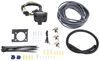
This time-delayed brake controller is designed to mount at any angle, even upside down. The controls are all up front for easy access, including a slide-bar manual override and a thumbwheel for braking output. LED indicator shows your braking status.
Features:
Specs:
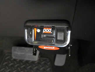
The Tekonsha POD is designed to mount in any direction, and it's especially suited for mounting on near-vertical dashes. All the controls are on the front of the module, so you can still access them with the controller tucked away in a convenient place.
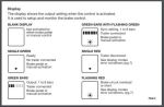
Braking output is the maximum amount of power that will be applied to your trailer's brakes. How much braking output you need is determined by the weight of your trailer; a heavier trailer will need more power to bring it to a stop. You want to set the braking output as high as you can without locking up the brakes. Once you've set up the brake controller the first time, you shouldn't need to adjust the settings until the trailer load changes, you switch trailers, or road conditions change. Use the thumbwheel on the side to change the braking output level. The output setting will appear as a number on the digital display, with a higher number indicating higher braking power.
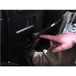
The Tekonsha POD keeps the manual override within easy reach on the front of the module, great for stopping sway or controlling your trailer's momentum in emergencies. Push the slide-bar lever to activate the trailer's brakes and brake lights without you having to apply the brakes on your tow vehicle, perfect for limiting trailer movement while you're cruising.
Because inertia plays no role in the functioning of this controller, you do not have to mount the unit at any particular angle. Your mounting options are limitless, with the controller designed with all of the controls on the front of the module so you can access them even if it's mounted upside down.
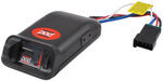
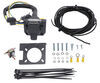
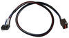
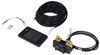
The included custom adapter easily plugs into the built-in port in your vehicle. Once you have the wiring connected to your vehicle, just plug the other end into the POD. Because there are no wires to splice, installation is not permanent. You can unplug and remove the brake controller at any time and securely stow it away.
Note: If you don't already have a 7-way plug at the back of your vehicle, take a look at our exclusive 7- and 4-way brake controller installation kit (ETBC7 - sold separately).
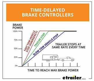
The Tekonsha POD comes equipped with time-delayed braking. Every time you apply the brakes in your vehicle, a signal is sent - via the brake switch - to the POD. The controller then sends power out to your trailer brakes to activate them with an intensity set by you, at a rate determined by you. The amount of braking power (output) can be adjusted to suit your preference, the road conditions, the type of trailer, and the weight of your load. To determine which levels are best for your application, test your towing setup and choose what feels right.
California residents: click here
Videos are provided as a guide only. Refer to manufacturer installation instructions and specs for complete information.
Speaker 1: Today on our 2009 Toyota Matrix we'll be having a look at and installing the Tekonsha Powertrac Electronic Brake Controller, part number 39523. All right, here's what our brake controller looks like installed. We have a trailer hooked up to it right now so you can see our LED indicator light. When you're hooked up, you have a green indicator. When you're not hooked up to your trailer there is no light, so you don't have to worry about it distracting you when you're driving your car normally.We have two key features on it. We have our manual override right here and our adjustment knob here for our gain.
I'm going to slide our manual override on over, and you'll notice as we adjust our gain, the LED changes from a green to an orange and then to a red. Now I step on our brakes, you can see how it gradually steps up intensity to a red if we don't have it adjusted al the way. This is a time delayed brake controller. It's not proportional, so when your foot is on the brakes, your brakes will be applied on your trailer at all times.This brake controller is a ideal cost effective solution for those looking to add a simple brake controller to their vehicle so they can control electronic trailer brakes. This controller will allow you to control up to two axles of brakes, so four brake assemblies in total.
What you would like to do with this controller is set it up so you have the most braking that you need. If you start to feel like you have too much brake, you can simply back down the knob to you're comfortable. The hillier the terrain that you're in or the heavier your trailer, you'll want more braking. If you have a lightweight trailer you won't need quite as much, and you can back it down a little bit to where you need it.Now our manual override feature is a simple operation. You just slide it on over, and the more that you slide it on over, the more brakes are applied to your trailer.
What this is ideal for is if your trailer starts to jackknife behind you and you need to bring it in line, you don't want to slow down your vehicle by stepping on your brakes because that'll just make the situation worse. You only want to slow down the trailer, so you just slide the manual override back on over, and that'll slow down your trailer and bring it more back in line behind you.Now that we've gone over some features of our brake controller, we'll show you how to get it installed. To ease our installation we'll be using the ETBC7 kit, which will convert our vehicle from a four flat to our seven way so we can use a brake controller on it, and we have all the necessary wire and breakers with that kit to install this into our vehicle. We'll also be using a no-drill long bracket, part number 18136, so we have something to mount our seven way onto our trailer hitch.All right, we're going to start our install out here on the table getting some of our wiring connections made so we don't have to do it on the car. We'll take our four pole flat connector here, and we're going to cut that off.
Now we'll strip back the three wires that we're in that, and we'll take some 14 to 16 gage heat shrink butt connectors, which we have available on our website, and we'll stick that onto those three wires and crimp them down.Black wire here is our 12 volt constant power, that'll go to our breaker. Our blue wire here is our output for our trailer brake controller. What we're going to do, they already have yellow butt connectors on them. We're going to cut these off, make them a little bit shorter. Strip them back and we'll replace these with some heat shrink 10 to 12 gage butt connectors, which we also have available on our website.Now, our purple wire here is for our reverse light input. If you have a function on your trailer, in case it has reverse lights or if you have a boat trailer that has a seven way connector with a reverse lockout solenoid, you would be using this. In this particular application we don't need it, so we're going to cut back this purple wire, still leaving some there in case we ever need to add it again, and we'll take some electrical tape and tape this up so it's secure. This'll help protect it from the elements in case we ever need it. I'm also going to wrap our wires up here next to our connector so we don't have any colored wires hanging out below our vehicle.Our white wire here is our ground wire. I'm going to cut off some of the excess here. Our vehicle already has a ground on our four pole flat connector, we're just going to tie that into it. Strip back some insulation. I'll use one of our blue heat shrink butt connectors on that again and crimp it on down. Now we'll slide our seven way mounting bracket onto all the wires and we'll secure it with the provided hardware. We have some long flathead screws, drop on down through, and then some star nuts, we have four of these in total. Now we use a wrench to hold the nut still while we use a screwdriver to tighten down the screws.Now we'll attach our seven way to our no-drill bracket. Drop down the screw, secure it with a nut and tighten those down as well. Now we'll take our bracket assembly here with the seven way and we'll stick it on and over our hitch, just this side here of our safety chain loops. We'll secure it with the provided clamp. Now that we have our clamp started, we'll run it down with a 5/16 nut driver. Make sure we have this exactly where we want it and at the right angle before we fully tighten the clamp. Right there looks level. Now we'll cut up our excess clamp with a pair of tin snips.Okay, now we'll turn our attention to our duplex wire. There's actually two wires inside this gray jacket. To access them, we'll take a utility knife and just slice right down the middle. We'll peel it back, and inside we'll find a black and a white wire. We'll cut the rest of this jacket off here and we'll strip back the insulation on both wires. Now we'll tape that to those two wires and we'll drop them down through the hole in our bracket. We'll pull it down here a little bit so we have some wire to work with. The black wire, we'll attach to our black wire. The white wire here we're going to attach to the blue wire.Now our four pole flat trailer connector, which we already had installed on the vehicle, we're going to cut off the end of it here. We'll separate all four wires, and we need to pull them back about an inch, that'll be fine. We'll drop that through the hole in the bracket as well. We'll find out how much wire we are actually going to need in order to connect these, so we'll separate our wires further on back towards that area and we'll cut off the excess.Start with our brown wire here first, this is our taillight circuit. Right about here will be fine. Strip that back and we'll combine that with the brown wire off of our seven way. We'll do the same for our yellow and green wires, those are our turn signal and our brake light circuits. The yellow one is our left one and the green one is our right one. Okay, that leaves us with our white wire, which is our ground.Okay, now we'll use a heat gun to shrink down our heat shrink butt connectors. This will provide us a secure and proper weather-tight connection against the elements. Now that we have all of it heat shrank and protected, we'll push it up through the hole in our bracket as high as possible so we don't have to worry about any wires dangling below our vehicle. Once we have it up there nice and tight, we'll wrap some wire loom around it and electrical tape to hide all of our colored wires.Once I have this partially on I'll put a zip tie around the end so our wire won't come out of the loom further on up. We don't need to be really tight on it, just enough to keep the loom closed. Then we'll just slide that up to where our four pole wire comes down. We'll wrap the rest up in some electrical tape. We'll do the same for our duplex wire. Even though we already have it heat shrinked, this will just help protect it even more and conceal any of the color wires underneath our vehicle.Okay, we stuck our duplex wire up and went above our exhaust heat shield here. This'll protect it from any of our heat. We want to make sure we avoid any moving parts and sources of heat. You see where it comes out from our heat shield, come up here to this wiring harness where we have it zip tied up. Went above our suspension here, then we zip tied it to our parking brake cable. This is inside of a sleeve so it doesn't move, so we don't need to worry about that. Then we continued zip tying it to that. Then we have it zip tied to all of our mounting brackets for our brakes and our fuel lines. That brings us up to our rear of the front sub-frame, right at the end of our fire wall.Now we'll drop down a pull wire from the engine compartment and bring this on up into the engine bay. Okay, with our pull wire attached down below, we'll just pull our duplex wire on up into the engine bay. Now we need to remove our gray protective sleeve that covers both our wires, and we need to move it down about as far as we can go, so down here where the wire comes up by our master cylinder will be a good spot to start. Once I get it to start, we'll continue the rest of the way down the wire.Okay, now we need to find a place to mount our two breakers. We'll be using a 40 and a 30 amp breaker. The 40 amp breaker is going to power our constant 12 volt on the back of the vehicle, which again is our black wire, and the 30 amp will power our brake controller inside of the vehicle. I'm going to mount ours on our driver side strut tower mount right here because it's really close to the battery and is a good, stable surface to mount them to, and it's not going to interfere with anything else in the vehicle. We'll secure these breakers in place to the strut tower with the provided self tapping screws.Now we need to measure off how much black wire we're going to need to connect to the auxiliary side of our 40 amp breaker. That's this terminal right here. This is our 40 amp breaker, the other one's our 30 amp breaker. The gold side of our terminal is the battery side and the silver side is your auxiliary. Measure off how much we're going to need, cut off the excess, strip back the insulation and we'll crimp on one of our small yellow ring terminals.Now our excess black wire, we'll strip back some insulation from one end and we'll attach another small yellow ring terminal to it. We'll attach that to the auxiliary side of our 30 amp breaker. We'll tighten down all these nuts when we're done, we're just leaving them finger tight now so none of our wire comes off.Now we need to pass our black wire into our fire wall. We need to find a good place to do that. This grommet here right to the side of our brake booster is a perfect spot. If we go to the top of the grommet above the wires, we will have a clean access to poke a hole screw. We'll use a screwdriver, poke it on through, now we insert our black wire. Now we'll go into the inside and pull it on down into the vehicle. Now we'll repeat the same process for the white wire.Now we can take our brake controller and we'll cut off our plug at the end. Our black wire here is our constant 12 volt power that powers it. We'll strip that back, take one of our butt connectors, stick it onto it, and we'll crimp it down. Now our black wire here that we brought into the fire wall, we'll measure off how much we're going to need. Cut off the excess, and save because we'll need it again later. Strip back the insulation and we'll attach it to the butt connector we just installed on the black wire off the brake controller.We'll cut off the same amount of wire for our white wire and we'll save it too, because we'll need it again. Strip back our insulation. Now, this is our output for our trailer brakes on the back of the vehicle that we attached to the blue wire on the seven way connector, so we'll attach that to the blue wire on the brake controller to another one of the butt connectors.Our leftover white wire, we'll strip off some insulation and we'll take one of our large ring terminals here, making sure it'll fit over the stud of the negative terminal of our battery. Stick it on and we'll crimp that down. This'll provide our ground for our brake controller. Now we'll get a socket and secure it underneath this nut here. Remove the nut, 12 millimeter socket, and place the ring terminal onto the stud and replace the nut.Now we'll pass this wire through the fire wall like the other ones. We'll pull that white wire on down. Now we measure off the same amount of that white wire as we did the other two wires, cut off the excess, and strip that on back. Take one of our yellow butt connectors, stick it on the wire, and we'll crimp it on down. Strip back some insulation from the white wire off the brake controller and we'll stick that in the other end of that butt connector. Since this is a smaller gage wire, we'll twist it together, fold it back in half. This'll give us more material to bite onto inside of the butt connector.Now for our red wire, I'm going to extend it with some extra red wire that we have laying around. You can use some of your excess white or black wire to do this, too. I'm just using the red wire that we have so it matches so you understand what's going on a little bit better. I'm going to double these up like we did earlier since they're a thinner gage wire, stick it inside our butt connector.Now that we have all our connectors off of our brake controller inside butt connectors, one thing I like to do is wrap them up in a little bit of electrical tape to help conceal them inside of the vehicle a little bit. I'll wrap all of my butt connectors individually here first. This just gives it a little extra security in case your feet might pull one of the wires, this might help keep it together a little bit better. I'm going to put some wire loom over our wires here too. This is some of the leftover from what came in our kit. We left our red wire out because we still have to make a connection for that.Okay, we're going to locate our stop light switch. It's located underneath the dash. This is our stop light switch right here. We'll push this tab on it and unplug it. I'm going to remove some of the factory electrical tape and loom over the wiring so we have a little bit more to work with, being sure we don't cut any of the wires inside. I'm going to be working with this blue wire. What we'll do, we'll cut it right here in the middle and we'll strip back the insulation from both ends.Now we're going to measure off how much of that extra red wire that we had that we're going to need, cut off the excess, strip back the insulation and we'll tie it in with one of the blue wires that we cut off of our brake light switch wiring harness. Stick it inside of our butt connector, crimp that down. On the other side we'll just reattach the other end of the blue wire. With that done, we can now plug back in our stop light switch.Okay, now we need to find a suitable place to mount our brake controller inside the vehicle. We typically want to have it to the lower right hand section of the driver's dash. That way, you don't knock into it when you're getting in and out of the vehicle. We'll use our bracket here and we'll determine what the best angle will be for our controller. Just like that should be good, so hit the controller on down and we'll secure the bracket in place to the dash with a couple of the self tapping screws. Now we'll attach the controller to the bracket with a couple more self tapping screws.Now we'll take our excess black wire and we'll strip off the insulation from both ends, and we'll attach ring terminals that are small to both ends. With those on there, we'll crimp them both down. Now we'll attach both of these, doesn't matter which end or which breaker. We're going to attach these to the battery side of our breakers, which again is the gold side. Now we'll snug up all of our nuts to our breakers. We're using a 10 millimeter socket for this.Now we'll take our black wires that go to our breakers, drape them over to where our battery is, and we'll cut off our excess wire, strip back the insulation on both ends, and we'll attach our two final large yellow ring terminals to those wires. We'll remove the 12 millimeter nut from the positive post on our battery and we'll drop on both of those to the stud, and reinstall the nut. That completes our look at and installation of the Tekonsha Powertrac Electronic Brake Controller, part number 39523 on our 2009 Toyota Matrix.
Do you have a question about this Trailer Brake Controller?
Info for this part was:
At etrailer we provide the best information available about the products we sell. We take the quality of our information seriously so that you can get the right part the first time. Let us know if anything is missing or if you have any questions.


Thank you! Your comment has been submitted successfully. You should be able to view your question/comment here within a few days.
Error submitting comment. Please try again momentarily.