


Finding Stoplight Circuit on 2004 Holiday Rambler Endeavor for Brake Controller Install
Published 10/09/2019
Products Featured in This Question
Question:
The problem is that the circuits lose voltage when the pedal is applied and this suggest to me that the brake light relay has constant voltage applied to keep it in open circuit, thus when the brake pedal is applied the brake circuit is closed by the lack of voltage. A rather complicated way to accomplish brake lights. I will try your suggestion and give you further follow up. Thanks for your assistance
asked by: David G
Expert Reply:
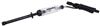
Your 2005 Holiday Rambler Endeavor is built on a Roadmaster Motorhome chassis which inconsistently has brake controller wiring like you have found. Since you can't find the stoplight signal wire the best option is to use a circuit tester like part # PTW2993 to test all of the wires that run to the brake light switch circuit on the brake pedal till you find a circuit that carries voltage only when the brakes are applied and use it to wire to the red wire of your brake controller and you'd be set. The switch on the brake pedal is what tells the stoplights of the RV to apply which is why the circuit you need happens to be there.



Continue Researching
- Shop: Roadmaster Direct-Connect Base Plate Kit - Removable Arms
- Shop: Brake Controller
- Q&A: 2004 Holiday Rambler Endeavor Model E40PST330H Break Controller Installation
- Shop: Demco Classic Base Plate Kit - Fixed Arms
- Shop: RoadMaster BrakeMaster Custom Seat Adapter
- Shop: Roadmaster 4-Diode Universal Wiring Kit for Towed Vehicles - 4-Way Flat Connectors
- Video: A Closer Look at the Hook Probe Circuit Tester
- Shop: Hook Probe Circuit Tester
- Search Results: battery charger
- Shop: Curt Echo Wireless Brake Controller - 7-Way Plug-in w/ Bluetooth App - Up to 2 Axles - Proportional
- Shop: Mighty Cord SurgeMinder Surge Protector and Circuit Tester - 50 Amps
- Search Results: rv surge protectors
- Q&A: Does Tekonsha P3 Brake Controller Need to Power Off When Not In Use
- Video: Replacement Battery Charger for Bright Way Trailer Breakaway Kit: The Breakdown
- Search Results: trailer hitch
- Article: Trailer Wiring Diagrams
- Q&A: What is the Difference Between a Class II and a Class III Hitch?
- Video: An In-Depth Look at the Roadmaster Diode 7-Wire to 6-Wire Flexo-Coil Wiring Kit
- Video: An In-Depth Look at the Roadmaster Battery Charge Line Kit for Towed Vehicles
- Q&A: Which is Better Roadmaster or Blue Ox Tow Bar
- Article: Brake Controller 7- and 4-Way Installation Kit (ETBC7)
- Search Results: trailer wiring
- Article: How to Measure for Trailer Hitch Drop
- Search Results: base plate for tow bar
- Video: Comparing Portable Flat Tow Braking Systems - Curt RVi and Blue Ox Patriot
- Video: Breaking Down the Roadmaster Diode 7-Wire to 6-Wire Flexo-Coil Wiring Kit
- Search Results: tow bar
- Article: Wiring Trailer Lights with a 7-Way Plug (It's Easier Than You Think)
- Q&A: Installation Time for Blue Ox BX1128 Flat Tow Base Plate Kit for 2016 Jeep Grand Cherokee
- Search Results: trailer tires and wheels

on Accessories and Parts







David G.
10/9/2019
The problem is that the circuits lose voltage when the pedal is applied and this suggest to me that the brake light relay has constant voltage applied to keep it in open circuit, thus when the brake pedal is applied the brake circuit is closed by the lack of voltage. A rather complicated way to accomplish brake lights. I will try your suggestion and give you further follow up. Thanks for your assistance