

How Does The Discontinued Power Gear 500210 Control Panel Make A Complete Circuit?
Updated 09/08/2025 | Published 10/11/2021
Question:
Hi: My situation is I have levelling jacks controlled by Power Gear 500210 control panel. I know they’re obsolete, but I want to know how the control panel controller is supposed to work before I invest in an upgrade system. As I understand, the hydraulic pump motor solenoid positive from the battery connects to a red wire that supplies power from + side of the battery to the 3 jacks actuator valves and 1 float valve. The colored wires also connect to the jack actuator valves and float valve to provide the grounding - which also connect to the 500210 Power Gear control panel via an 8 pin connector. To actuate each jack the controller grounds - the colored wires connected while the red wire provides the positive side + to each jack actuator valve thereby completing the circuit. Not accounting for the blue wire that connects to the hydraulic pump motor solenoid to acuate the hydraulic pump motor. Current situation, the jack valve-colored wires that provide grounding - for the four valves in 8 pin connectors to the controller are hot +. The black ground wire is connected to the negative side of the battery. If the red wire is disconnected from the solenoid, the colored wires cease to be hot. Questions: 1. How does the controller create a complete circuit? 2. Are the colors wires orange, yellow, green, and brown supposed to provide grounding? 3. Simply grounding the colored wires since they are hot creating a direct short correct? 4. For the 8 pin connector the blue wire connects to the solenoid to acuate the hydraulic pump and the black wire is the ground wire connected to the negative side of the battery?
asked by: Jeff C
Expert Reply:
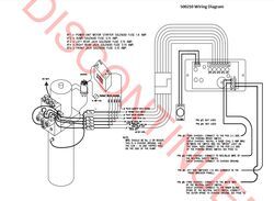
I found an old wiring diagram for your now discontinued Power Gear 500210 control panel and it really helps show how things are supposed to work.
There is a red wire running to the three jacks, the dump valve, and the float valve from the solenoid. The solenoid then has a power wire run to the controller.
When you press the buttons on the control panel the solenoid opens and sends power to the jacks as needed which is what completes the circuits, and the wires run off getting power not getting ground.
You would not want to ground these power wires or you would get a short and blow the fuses on the back of the controller.
The blue wire you mentioned is the correct power wire running to the controller from the solenoid, and the black wire is the ground to the negative terminal of the battery.
If your system is not working correctly anymore you will need to replace the control panel with the Replacement Lippert Power Gear Manual Leveling Control Kit # LC359259 which is a confirmed replacement for your 500210 control panel.
I included a video review of the # LC359259 for you to take a look at.

(click to enlarge)

Product Page this Question was Asked From
Replacement Lippert Power Gear Manual Leveling Control Kit

- Accessories and Parts
- Camper Jacks
- Trailer Jack
- Controllers
- Control Panel
- Lippert
more information >
Featured Help Information
Miscellaneous Media

Continue Researching
- Shop: Replacement Lippert Power Gear Manual Leveling Control Kit
- Q&A: Power Gear 500210 Replacement For A Milwaukee Cylinder Board For A 1998 Chevy Southwind Storm
- Video: All You Need to Know About the Replacement Lippert Power Gear Manual Leveling Control Kit
- Search Results: fabric
- Q&A: Replacement Power Gear Control Panel For a 1996 Fleetwood Discovery
- Search Results: vehicle tow bar wiring
- Shop: Trailer Hitch
- Shop: Trailer Wiring
- Q&A: Installation of Manual Leveling Control Kit On P30 National Dolphin
- Search Results: trailer brakes
- Search Results: dome light
- Q&A: Power Gear 500210 Replacement Touch Pad Control Unit
- Shop: B&B Nautilus P3 RV Water Control Panel - 10" Tall x 15" Wide - Polar White
- Q&A: Replacement Control Panel for Power Gear 500210 Leveling System of RV
- Shop: Replacement Control Module for Lippert Ground Control 3.0 Leveling System - Prepped 5th Wheel RV
- Q&A: Replacement Control Panel for Leveling System on 1995 Fleetwood Motorhome
- Shop: RV Roof Membrane
- Shop: Replacement Lippert Control Panel with Amp Connector for 4-Point Leveling System
- Shop: B&B Dual RV Water Inlets - City Water and Gravity Fill - Brass Check Valve - Polar White
- Shop: B&B Dual RV Water Inlets - City Water and Gravity Fill - Plastic Check Valve - Polar White
- Shop: Quick Roof Repair Tape for RV Roofs - 10' Long x 4" Wide - White
- Shop: Suspension Enhancement
- Q&A: Replacement Leveling System Control Module for 1994 Fleetwood Bounder
- Shop: Vehicle Tow Bar Wiring
- Shop: Base Plate for Tow Bar
- Video: Installing the Roadmaster 4-Diode Universal Wiring Kit on a 2024 Ford Bronco
- Video: Comprehensive Review: T-One Vehicle Wiring Harness with 4-Pole Flat Trailer Connector-118751
- Video: Second Vehicle Kit for Roadmaster InvisiBrake Flat Tow Brake System Spec Review
- Video: Roadmaster InvisiBrake Second Vehicle Kit Installation - 2018 Jeep JL Wrangler Unlimited
- Video: Hands-On with the Mount-n-Lock SafetyStruts Standard RV Bumper Support Brackets
Chris S.
9/6/2025
Hi Samuel Is there any place in Australia I can get this replacement control panelLC359259, cheers chris