

How to Wire the 3rd Brake Light Logic Module Using an RV 7-Way Trailer Connector
Updated 02/16/2021 | Published 02/11/2021
Products Featured in This Question

Question:
hello, I believe that the logic module that I got is defective. I wired it according to the diagram enclosed and it did not filter out the flash. I am using it with a 3rd brake light using a trailer plug. Your website offers this :How To Power Third Brake Light On Camper Shell Using 7-Way Trailer Connector Can you please send me a diagram? I have tried to wire it with every way I could, no way has worked. The answer is confusing feeds into output The module has 3 wires please could you providehow to wire diagram. or please explain what is the input, what is the output, do you wire in-line or splice into? with a splice, the light works in every way but still flashes. Using the directions in this answer, the light does not work at all. with clear directions it will be clear that there is no wiring mistake. then, if it still dose not work, I will know for sure if the part is in-fact defective. Thanks for your help
asked by: Marlene
Expert Reply:
I understand your frustration with wiring the 3rd Brake Light Logic Module, part # PP20-702. The wiring diagram provided is not very comprehensive. While we do not have another diagram to send, I can explain this in clearer terms.
The module is meant to receive the input from the left and right brake signals from the vehicle and filter them so that the turn signals do not show, leaving only the brake signal.
This is achieved by wiring the two yellow wires into the left and right turn signal functions on your vehicle, and wiring the green wire to the power of the new light.
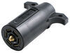
If you are using the Pollak Black Plastic RV-Style Trailer Connector, part # PK12706, like in the question you referenced, then you will need to wire the two yellow wires of the module to the Left Turn and Stop and the Right Turn and Stop as labelled on the picture I have included (these are labelled with green and yellow lines in the diagram, but just know that it's the two yellow from the module that you'll using. Ignore the fact that green is chosen to represent the Right Turn and Stop in this particular diagram).
After wiring the two yellow wires into those points (it doesn't matter which goes to which, so long as one goes to Left and the other goes to Right), then you will wire the green wire of the module to the 12V source of the new light.
If you are not using a 7-way RV style trailer connector or if you're vehicle's harness is not a 7-way, let me know and I will explain further.


(click to enlarge)
Product Page this Question was Asked From

Featured Help Information
Instructions

Continue Researching
- Shop: 3rd Brake Light Logic Module
- Search Results: bedslide truck bed slide
- Shop: Pop & Lock Power Lock Conversion Kit for Truck Caps and Hard Tonneau Covers
- Shop: Trailer Wiring
- Search Results: curt t~connector vehicle wiring harness
- Video: Review of JR Products RV Sewer Hose Fittings - Exterior Evacuation Drain Trap - 37295195
- Search Results: 3/4" drain hose
- Search Results: sink strainer
- Search Results: waste valve
- Video: Complete Breakdown of the 3rd Brake Light Logic Module
- Video: Review of Camco RV Sewer Hose Fittings - Sewer Drain Traps and Connectors - CAM37262
- Video: Plastic Sink Strainer w/ Threaded Basket for 2" Drain Spec Review
- Video: Feature Review LaSalle Bristol RV Shower Drain w/ Grid Strainer
- Shop: Truck Bed Sliding Tray
- Shop: LaSalle Bristol RV Shower Drain w/ Grid Strainer - 1-7/8" Diameter - Parchment
- Shop: LaSalle Bristol RV Shower Drain w/ Grid Strainer - 1-7/8" Diameter - Chrome
- Shop: Plastic Sink Strainer w/ Threaded Basket for 2" Drain - Chrome
- Shop: Exterior Evacuation Drain Trap
- Shop: Valterra Waste Valve for RV Gray Water Tank - 1-1/2" Diameter - Spigot to Hub
- Q&A: Powering 3rd Brake Light and Dome Light on Topper for 2025 Silverado 1500
- Q&A: How To Power Third Brake Light On Camper Shell Using 7-Way Trailer Connector
- Q&A: Can You Use The 3rd Brake Light Logic Module With A 4-Pole
- Video: Best 2015 Kia Sorento Trailer Wiring Options
- Q&A: Making 7-Way to Camper Shell Third Brake Light Adapter
- Q&A: How To Power Third Brake Light On Camper Using Trailer Connector
- Video: Trailer Wiring Harness Installation - 2015 Kia Sorento
- Q&A: Wiring and Connectors to Power 2025 Ford Maverick Truck Cap 3rd Brake Light
- Q&A: Standard Color Code for Wiring Simple 4 Wire Trailer Lighting
- Search Results: camper jacks
- Shop: Vehicle Tow Bar Wiring