


Wiring 2009 Land Rover LR2 for Electric Trailer Brakes
Updated 02/03/2010 | Published 02/02/2010
Products Featured in This Question

Question:
I have Land Rover LR2. Not many options I can see for this car. The car has factory connector I believe 4-pin. I would get the kit to make it 6-pin for small horse trailer, part # 37175. However, I wonder how I should connect blue wire for electric brakes in this car. Please help.
asked by: Maciek
Expert Reply:
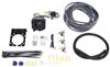
To actuate the electric brakes on the horse trailer, you will need to install a brake controller in your Land Rover. I would recommend a proportional controller, such as the Tekonsha Prodigy P2, part # 90885. The Prodigy is one of our best selling controllers, has been for years primarily because it works great and is very easy to use. You will also need the Brake Controller Installation Kit with 6-way connector, part # ETBC6, which includes the adapter you were mentioning.
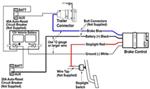
The installation kit includes everything necessary to complete the installation. The 4-pole to 6-way adapter included in the kit would plug into your existing 4-pole connector, with 3 wires remaining. The white wire would ground to the vehicle, the blue wire would run to the cab of the vehicle via the engine compartment and attach to the blue brake output wire of the brake controller. The red wire from the adapter can be used to supply 12-volt auxiliary power to the trailer, it would run to the positive battery terminal via the 40 amp inline circuit breaker included in the installation kit.
The controller itself would mount under the dash inside the vehicle within close reach of the driver, typically to the right of the steering column. The brake controller will have 4 wires exiting the rear of the unit. The black wire would run through the firewall to the positive battery terminal via either the 20- or 30-amp circuit breakers included with the install kit (depending on which is recommended by the brake controller manufacturer). The white brake controller wire would run through the firewall and attach to the negative battery terminal. The red wire would attach to the brake stoplight switch, located at the top of the brake pedal. You would need to use a circuit tester like part # PTW2993 and test each wire exiting the switch, tap the red brake controller wire into the brake stoplight switch circuit that only shows current when the brake pedal is pressed. The remaining blue brake output wire would attach to the wire that was run from the trailer connector at the rear of the vehicle.
We have a brake controller install guide that you might find helpful, as well as an installation video. I will include links below to these as well as to the parts I have recommended.


Product Page this Question was Asked From
Adapter 4 Pole to 6 Pole and 4 Pole Trailer Wiring Adapter


- Custom Fit Vehicle Wiring
- Wiring Adapters
- Universal Fit
- 4 Flat to 6 Round
- Plug and Lead
- Hopkins
more information >
Featured Help Information
Miscellaneous Media


Continue Researching
- Q&A: Where to Mount Breakaway Switch of Blue Ox Patriot Braking System on 2017 Jeep Cherokee Trailhawk
- Q&A: What Bracket Goes With The TowSmart ProClass Trailer Connector TS59RR?
- Q&A: Does Tekonsha to Redarc Adapter work with Tekonsha 7-Way Wiring Kit of 2021 Toyota Highlander
- Q&A: Is the Reese Under-Bed Kit the Same as the OEM Puck System for a 2024 Ford F-250 Super Duty?
- Q&A: Correct Replacement for AL-KO 568182 or Hayes 09089324
- Q&A: Is There a Replacement Hub For a AL-KO 7170 Trailer Hub?
- Q&A: Looking For 18" Long 4-Flat Trailer Extension
- Article: Trailer Wiring Diagrams
- Article: Brake Controller 7- and 4-Way Installation Kit (ETBC7)