


How Does the Universal-Design Rocker Switch Wire to Circuits
Updated 01/19/2016 | Published 01/18/2016
Question:
Wiring diagram for switch to operate hydraulic motor and directional solenoid
asked by: Dave
Expert Reply:
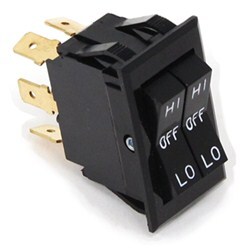
On the part # PK34312 that you referenced the two pins in the middle that are perpendicular to the ground are the ground circuits for each side of the switch. Now the power for each corner of the switch is at the terminal that is directly behind the push button. So the terminals in the four corners are the power wires for each circuit.
Basically this can control the power for up to 4 circuits and you would need to wire them up to the switch accordingly.


Product Page this Question was Asked From
Universal-Design Rocker Switch - Dual Actuators - DPDT - High-Off-Low - 12 Volt - 20 Amp

- Accessories and Parts
- Wiring
- Switches
- Rocker Switches
- 20 Amp
- Pollak
more information >

Continue Researching
- Q&A: Does the Lippert OneControl ConnectAnywhere Cellular Upgrade Kit Require a Data Plan?
- Article: Electric Trailer Brakes: How They Work & What to Buy
- Q&A: Parts Needed To Install Brake Controller in 2015 Audi Q5 with 7-Way
- Q&A: Replacing 6-Way on Trailer With 7-Way Connector
- Q&A: Solution for Von Weise Fifth Wheel Landing Gear with Bad Motor
- Q&A: RV Cover Recommendation Retro Style 189R by Riverside
- Q&A: Recommended Hitch for a 2023 Fleetwood Fortis on a F53 Chassis
- Q&A: Replacement RV Microwave for High Pointe EM925ACW in LQ Horse Trailer
- Article: Trailer Wiring Diagrams