
Westin Pro-E Power Motorized Running Boards with LED Lights - Black Aluminum


To see if this custom-fit item will work for you please tell us what vehicle you'll use it with.
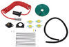
These custom-fit, motorized running boards automatically deploy as your vehicle's doors open and retract when the doors close. Integrated LEDs enhance safety and visibility. Easy installation with included hardware and mounting brackets.
Features:
Specs:

California residents: click here
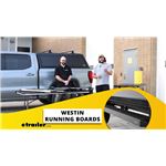
Videos are provided as a guide only. Refer to manufacturer installation instructions and specs for complete information.
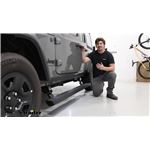
Hi everyone, Aiden here with Etrailer. Today we're gonna be taking a look at and showing you how to install the Westin Pro-E Powered Running Boards on our 2023 Jeep Wrangler Unlimited. Now the advantage of a powered running board is that when they're not in use and you're driving, it's gonna be tucked up neatly against the side of the vehicle or just when it's parked. It's gonna be tucked up and look really neat. It sits pretty flush against the rocker panel here and when you are ready to go, it'll trigger with any one of the doors opening, deploys very quickly, and gives you a nice wide step to help get into your vehicle. The step itself is made of aluminum, which is going to be the most rest resistant and it's gonna be six inches wide, so good for some larger feet or boots and you don't have to worry about it being a really narrow step.
The powder coat on here doesn't have much of a texture, so you're really gonna be relying on the ridges here to give you grip. So if it does get wet, you might notice that it's a little bit slick, but that's what those ridges are there for to help grip into the tread of your shoe. As far as the weight capacity goes, you're gonna be working with 300 pounds per side and I'd say I feel pretty solid on these. You definitely feel a little bit of flex whenever you step on them, but that's pretty normal for most running boards, I'd say compared to some of the other ones I've installed that this one gives me a little more confidence given that the step is so much wider and there's sensors in all four of the doors. So whether you're opening the driver, passenger, or rear doors, it's gonna deploy those boards and it is side specific.
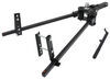
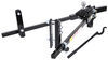
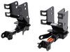
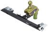
So right now, only the driver's side is deploying. The passenger side operates independently. So if it's only you getting in and outta your Jeep to drive it, then only this side will deploy. Now the mounting brackets, motors and hinges are all one solid unit and they're really solid. They utilize factory holes to mount up so there's no drilling required and you get two per side, one for the front, one for the back.
You also get two lights per side, these little LEDs that will shine onto the steps. So if you're using these at night, you get a little bit of illumination. Again, two per side, so whether you're using the front or the back doors, you've got that extra visibility. In your driver's seat, you're gonna have a manual override switch. It's in the on position right now, which means that the boards will deploy whenever we open the doors.
Flipping it off will cause them to retract and basically render them useless. They won't operate at all until we turn that switch back on. On the passenger side of the vehicle, you're gonna have your control module, which is essentially the heart of the whole system. Every wire and connector will come back to this and your power and ground wire will come from here to your battery as well. So all the connections that we make for both the LEDs, the board, the sensors, they all come back to here. This is the central unit and it's gonna be protected by a steel panel that wraps it all up and just keeps that protected from any rocks or debris that get kicked up under. The motors are IP68 rated, which just translates to a really high water intrusion resistance and on the front side where the motors are pointing down, and you may be worried about clearance, again, you've got protective steel covers all around there just to keep them safe. As far as the installation goes, it's gonna be pretty straightforward, but time consuming, I'd recommend maybe just setting a day on the weekend aside to tackle it. Not that it's a difficult install, just that it's gonna be time consuming. I know I've said a couple times now, no drilling required, so that part's really easy, but the wiring is gonna take the longest 'cause you gotta think. There's a wire for all four door sensors. There's a wire for each of the motors and each of the LEDs and it just adds up. Due to the limited space on the inside of the Jeep, running those interior wires might be a little tricky, but we'll walk you through the whole process right now so you can see how it installs. Now you can break your installation up into two main parts, the installation of the boards themselves and all the wiring components that go with them. We're gonna start with just the boards and that part is pretty straightforward. Each side is going to have two motor mounts, which pretty much they're all assembled, you just gotta bolt them on, and you gotta identify which one is for the front and which one's for the rear. The best way to do that is to just look at the bottom here where they're labeled. So rear right is for the back passenger, front right would be for the front passenger and then left will be for the driver's side. Now the kit's gonna come with a series of M8 bolts, one set of shorter ones and one set of longer ones. They'll all get lock washers and flat washers, which are the same, and the hardware combination for the front and the rear motor mounts will be slightly different. So for the front, you're gonna get two of those shorter M8 bolts and one of the longer ones, the shorter ones will go in to these threaded holes on the side and the longer one will go up through this middle slotted hole straight up. And for the rear, it's going to use just three of the longer ones, same places that you're gonna install it. The only difference there is that on these side locations, you're gonna have a spacer block and that's why you need the longer M8 bolts there. Finding locations is pretty easy too. In the pinch welds, there's going to be some existing holes that'll line up with the threaded holes on our motor mounts. And then directly behind that on the rocker panel, you should see a single threaded hole centered between those two and that's where that center slotted hole is going to line up. So I've got the front motor mount with me right now. I'm just gonna get it loosely installed using that hardware combination we checked out earlier. Now the ones that go into the rocker panel can be hard to reach, so a socket with an extension can help extend your reach a little bit and make it easier to thread those bolts in. Now by hand, I'm gonna run this up most of the way, really just until those bolts make contact with the lock washer. That way, there's still a little bit of wiggle room here if need be. And just repeat that process for the rear. The rear location might get a little confusing because there's two sets of holes here, but again, just look to the rocker panel. There's only one threaded hole, so that helps us figure out which of these holes in the pinch weld we need to utilize. So I'll hold that spacer block up in there, use the bolt to keep it aligned. Luckily it kind of rests on that ledge there, so if you get one started, it becomes a lot easier to get the second one in. Now you may have noticed on the front motor assembly, the motor's pointing straight down, which isn't gonna be great. Once this is all installed and you're maybe using your Jeep off road so you've got a protective cover to basically protect that. They're all labeled again so front right and front left. So for our passenger side, we've got front right, and the hardware combination is going to be very similar, bolt, lock washer, flat washer only. This time, we're using M12 hardware for these locations. Now for each, there's no threaded holes that we're going to. So the bottom location's going to get this block that'll sit in our frame. And then for the side location, there's going to be this nut that we can feed in sideways to the frame. You'll see it a little bit closer when we get up there, but we're gonna start with the bottom mount location because that's the hardest one to get to. It's a good idea to mock it up and make sure that you have your orientation correct. So that top mounting location should line up with this large slotted hole. And below that, there's going to be a smaller slotted hole that the bottom tab will line up with. So like I said, we're gonna start with that bottom block first. You can feed that up through and kind of guide it back until you see the threads poking out right there. That's perfect. I'll take my bracket and start to thread in the bolt. Be very careful with this. You don't wanna push it out of alignment, so just gently try to thread it in. If you kind of push it out of the way, you can move it back until you get those threads that catch. There we go. Once it does catch, it'll hold itself. I'm gonna run it down just a little bit more, but enough that we can still move things around for this upper location. There's access hole on the backside of our frame rail directly up from where we just we inchesre working. And on the other side, you can usually see where that's lining up. I'll keep holding that piece of metal on the other side while I thread this in. This one's a lot easier and we're gonna immediately tighten and torque this hardware to the specifications found in our instructions because the protective cover isn't gonna interfere with the fitment of our board. Now if you don't have a torque wrench, you can pick up one here at etrailer or you can typically check one out or rent one from a local auto parts store. Now your running board is going to have a track on the underside with some T blocks that should line up with our motor mounts. There's gonna be some cutouts that are shaped exactly for that and each of those T blocks will get two of these little cap screws feeding up from the bottom into those threaded holes. So we'll grab an extra set of hands to help us lift this up to the Jeep, get it lined up and add these screws. We've got Joe helping us lift this into place and I'll kind of just peek underneath, make sure I've got those blocks lined up and it'll tilt down into place and you can feel it lock in. Once you do, just get one of those screws started by hand on either side so it holds itself into position. Maybe rotate it around if you need to, but you should feel it catch and when it does, it'll support itself. And before we go back through and fully tighten up all four of those cap screws you put in, I'm gonna just check my positioning side to side here and use some point on the Jeep as a frame of reference. We already got this side mostly aligned. I just wanna tap it towards the back a little bit. That seems to be the best way to slide it and make these minor adjustments. I've already got it lined up with the other side though, so I'll go back through and tighten it up. And with that evened up, we can go back through and torque the remaining hardware on our motor mounts. Now the control module is also gonna go on your passenger side. It's going to use your last two remaining M8 bolts, the shorter ones, and it's going to match up with two more holes just below the passenger door on that pinch seam. So just like we did before, loosely install and these can immediately get tightened and torqued down just like all the other M8 hardware. And then you just repeat those same steps that you took on the passenger side, on the driver's side running board, except on this side, there's no control module. That's only gonna be for the passenger side. And at this point, we're gonna go into the latter half of our install, which is gonna be all the wiring. It's plug and play, but the big thing's gonna be routing them safely so they're out of the way and finding the grommets to get inside the vehicle. We'll get that taken care of and show you the pathways that we took. Now in order to clear a path for our wiring, there's a few panels we need to get out of our way. First up is going to be this panel on the door sill. And the way you're gonna get that removed is by coming to the inside here where there's a small seam. You can get your thumbs in here and just push outward. You'll hear some clicks. So we don't need to fully remove this panel here, just enough that we can get underneath it and pass wires through. Now we need to turn our attention to the carpet. On the floorboard, there's a small part here where we can see a rubber plug underneath, that's a drain hole and that's how we'll get our wires inside. If we turn our attention up to near the center console, there's gonna be a button here where you can kind of get your hand in on the carpet, pop that button loose and start to peel this back. We'll keep pulling this towards us until we can get access to that plug that we saw earlier and just set that to the side. Now the wiring harness for your kit is a lot. It's big and it's got a lot going on, so it's maybe a little bit daunting at first. But right now, the only thing we need to pay attention to is this black wire lead, a white wire lead and a brown wire. The white and brown wire will have bullet connector ends and this black wire will match up with the manual switch. These are the three that we're gonna feed up through that drain hole we just exposed on the passenger side of our vehicle and just pull that slack up through. So it might be hard to see, but just above the frame rail is where that drain hole is. So I'm gonna try to feed these up through and see if I can catch it from the top side. So it's pretty messy right now. I've kind of jammed the drain plug back in, so it'll hold itself in. I can add a piece of electrical tape to hold this down so it doesn't fall back through. And we can make a small slit on here so that it sits cleanly, but I pulled everything up through all the way until the wire loom there so that it'll sit flush under the carpet again, but so that there's no bare wire poking down through exposed. Now we've done the same thing on the driver's side where we pull up that panel and pulled back the carpet a bit and just under the dash near our center console, there's a easy pass through where we fed an air line tube through and we're gonna pull over the white and the black leads. And if it's getting caught, maybe have an extra set of hands on the other side to feed it through. But those are the ones we wanna pass over here. Now we're using some electrical tape to make sure that these wires lay flat underneath the carpet, that they're not pulled completely tight so that we can't lay the carpet back down. Now we have pretty limited space, but my videographer Tom's gonna help me show where we routed the brown wire on the passenger side that went from underneath the carpet all the way under that panel that we popped up earlier and towards the B pillar. And that panel in the rear door seal, just removed the same way as the first one, and that's where the brown wire over here ended up popping out. Now with the brown wire routed, we're going to walk through the process of the door switches. Now these are the magnetic induction modules which will detect whether the door is open or closed. They're gonna have adhesive backing on the backs of the modules themselves and the wires leading up to it. And you'll notice a female end of the bullet connector that'll match up to that brown wire we just routed. And on the other end, we've got this small forked connector, which will go to a factory stud for our ground. Now we actually pulled our brown wire back a bit because that connection to the induction module is gonna happen just towards the rear of the front door and be tucked up in here. What actually got fed through was the other induction module and the forked ground connection that'll happen in the rear. To attach the module, we're gonna clean the surface area just below our latch here so that we can get a nice clean adhesion to the surface. And you will need a tape measure to match this up because you want the magnets to align when the door opens and closes. So what we're shooting for is 1-1/2" below the center of our latch. So I get that lined up as best I can. It's gonna sit sideways like this, and I'll try to center it up with those bolts as best I can on this rectangle here. And the 1-1/2" measurement is not going center to center, it's going center to the top edge of this module. So right about there is what I'm looking for. I'll peel that backing back and grab my tape measure again, just to confirm I haven't shifted it around too much. And we will do the same thing with our adhesive backing on this piece, routing it all the way back behind the B pillar to try to just give us the cleanest look with minimal wires as possible. And we routed the magnetic induction module much the same on the rear, only this time it was mounted in the center of this lower door hinge. Now the only thing we need to do is take this forked ground and go to a factory ground location, which under this panel, there's a series of studs and a factory ground pretty far back that we'll use. So we'll take our 10 millimeter socket to loosen that up enough to slide that fork in there and then we'll tighten it back down. Now to trigger those magnetic sensors that we just installed, you're gonna need a second side to it that will attach to the door. Now the front is going to be a lot easier because this latch is going to be our reference point. Go from the center 1-1/2" down, and that's where this will go. Same deal where it's got adhesive backing on it. The rear is gonna be a bit harder to see though. So we mounted our sensor between the bolts on our hinge here on the opposite side on the door, there's gonna be this foam kind of plastic up here. We want to go at the bottom of it, measure about 1/2" down, and that's where the magnet's gonna go on the door so that they line up when it's closed. With all the sensors mounted up and all the wiring cleaned up inside the vehicle, the last thing is that black wire we routed over to the driver's side too, and that's for our manual on off switch. So the two ends just plug together. There's gonna be a lot of excess wire, but we can tuck that up where we routed through the center console and there's adhesive backing to mount the switch up wherever you see fit. And here's where we chose to mount that switch with the wiring tucked right up under here. So we see as little of it as possible. And if your leg may rests against the side here, it doesn't bump into that switch accidentally. Back underneath the vehicle, it's more wire routing, but this time, it should be a little easier to see. For the most part, we're gonna be following the frame rail, but we'll show you the specific paths we took afterwards. The main premise of what we're doing though, we've got a bundle of wire leads right here that'll go to our control module, and then a series of longer leads that have the smaller connectors and these small circular connectors here, they'll also be labeled, this one is rear right and the one over here is front right, so that's gonna be my passenger side for the rear motor and the front motor. We'll start plugging these in and show the route we took, and lots of zip ties later, here's the path we took for our wiring. Starting from the module box, we connected all of our connectors. There's one of each so you can't mix them up, they just match up to the one that looks like them. We branched out to the rear motor assembly and here's our connector for the light, just kind of hanging out waiting. Then the connection for the front motor assembly on our passenger side, just again, straight line path. Here's our light connector and then tucked up there is everything that went inside the vehicle earlier, whereas all the other bundle of wires pass over the frame to this cross section here where we used some zip ties and some pads to stick this to the side where it's not gonna be getting hit with debris and tried to keep it as far away from this heat source as possible. Passed it back over the frame rail into the other side. That other side pokes out to our front left. Here's that light connector. And then again, everything just stays on top of the frame rail for pretty much the entire duration to the rear motor assembly. And here's that final light connector. So with all that, we can mount up our lights and route our power wire and that power and ground wire we routed following this factory wiring. The duplex wire was added later, but this wire behind it is factory. So we just followed that where it passed over top the frame rail and works its way up into the engine bay. The lights install really simply, adhesive backing on the back like we've been using all throughout and just plugs into those connectors that we showed all throughout. You wanna clean the surface and the mounting locations we're going for on the front will be just to the inside edge of the protective cover. And that goes for both sides. And on the rear, there's gonna be this series of factory holes. We're just gonna go between all of those. So all the lights will sit on the inner edges of the motor mounts, so we'll clean off those surfaces, mount it up, and take care of any loose wires that remain. Now with these connectors being plug and play, the two larger ones, you can't mix those up, they're different sizes, but the two LED connectors are the same style plug, but there are specific orientations. So the interior of one plug will be red, the interior of the other will be black. Make sure black goes to black, red goes to red. It's really easy to miss, especially if you've got limited visibility under here. But that's gonna make sure that your lights actually work whenever you go to test this. And just repeat that process for the other three locations. With the lights installed, we'll bring it back down and get our wires in the engine bay connected to power and ground, add our fuses and do all of our final testing. The wiring pops up in the engine bay really close to our battery, and we just followed along this factory wiring here where we went to our power and our ground, red to positive, black to negative and added in our fuses. Now it's important to note, remove those fuses before you start hooking things up because they do come pre-installed and your kit comes with extras. So pull these out, hook up those ring terminals and add the fuses last. Now as far as your final testing goes, you want to go around for each door, open it up, and one, make sure the boards deploy, but also that both LEDs turn on. You want it to retract whenever you close the door and work for both the front and the rear. The boards are also side specific, so this is just testing the drivers. We'll test the passenger side too, but we also wanna make sure that that manual override switch works. So right now, the boards are deployed, but if I hit that switch and turn it off, they should retract. And now the door function shouldn't do anything until I turn that switch back on and now they're operating with the door again. And then after testing the passenger side, verifying that everything works, that'll do it. The installation really isn't too bad overall, it's gonna take a while to run all the wires and make sure it's clean. And the interior of your Jeep isn't the biggest, so you don't have the most room to work in there, but everything's plug and play and overall, pretty simple. But that'll do it for our look at and installation of the Westin Pro-E Power Running Boards on our 2023 Jeep Wrangler Unlimited. Thanks for watching.

It took about 4 1/2 hours. It went very well and they are working wonderful Nick exceed my expectations.
Very satisfied with the Westin motorized running boards but mildly disappointed that they did not come with mounting hardware for the command module, similar to the mounting hardware for the four motors.
Info for this part was:
At etrailer we provide the best information available about the products we sell. We take the quality of our information seriously so that you can get the right part the first time. Let us know if anything is missing or if you have any questions.


Thank you! Your comment has been submitted successfully. You should be able to view your question/comment here within a few days.
Error submitting comment. Please try again momentarily.