

 Arrives before Christmas
 Thank you! Your comment has been submitted successfully. You should be able to view your question/comment here within a few days.
Error submitting comment. Please try again momentarily.
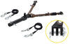
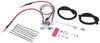
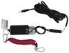
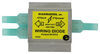
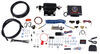
Relay works with your tow bar wiring system to ensure that your towed vehicle's turn signal lights flash in tandem with your RV's lights.
Features:
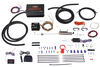
The purpose of a brake light relay kit is to prevent your towed car's brake signal from overriding the turn signal that comes from your RV. When your towed vehicle is properly wired and connected to your RV, its indicator lights will illuminate as you engage the turn signals in your RV. However, if you have only a four-diode system in place, the turn signal will be overridden by your towed car's brake signal as soon as your supplemental braking system presses the towed car's brake pedal. As a result, drivers behind you know only that you're slowing down and not that you are turning.
Installing a brake light relay in your towed vehicle fixes this problem by ensuring that your car's brake signal does not override the RV's turn signal. Therefore, your towed car's lights will function in accordance with your RV at all times.
Is a Relay Required?
To determine if a brake light relay is needed to properly wire your vehicle to be towed, answer the following questions.
Are you using a supplemental braking system that depresses the brake pedal in your towed car?
No - You do not need a brake light relay.
Yes - You may need a brake light relay. Continue on to the next question.
Do the brake lights on your towed car illuminate while the engine is off?
No - You do not need a brake light relay.
Yes - You may need a brake light relay. Continue on to the next question.
Do your towed car's brake lights act as both the brake signals and the turn signals?
No - You may need a brake light relay. Continue on to the next question.
Yes - Your towed car has a combined lighting system. You will need a brake light relay to ensure proper activation of its signal lights.
Does your towed car have separate brake lights and turn signals?
No - Your towed car has a combined lighting system. You will need a brake light relay.
Yes - Your towed car has a separate lighting system. You may need a brake light relay. Continue on to the next question.
Are you wiring your vehicle with a six-diode kit or a TowDaddy custom wiring harness?
No - You will need a brake light relay to ensure proper activation of your towed car's signal lights.
Yes - You do not need a brake light relay.
Most towed cars require the normally open installation method. Ford and Lincoln models with neutral tow kits and most automobiles that have a push-button start function will require the normally closed installation.
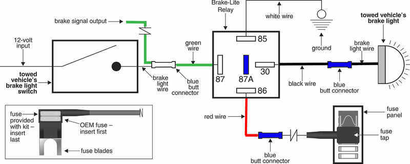
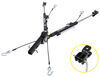
Normally Open
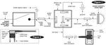
The diagram and steps shown below demonstrate the installation for normally open applications. Be sure to follow the instructions included with your relay kit for a more detailed process.
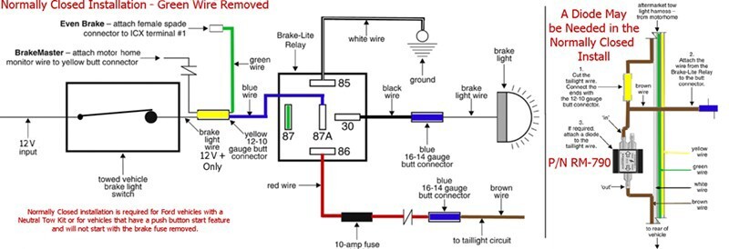
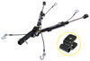
Normally Closed
The diagram and steps shown below demonstrate the installation for normally closed applications. If you have a Ford or Lincoln that has a neutral tow kit or if your car has a push-button start feature that will not start the engine when the brake fuse is removed, then you need to perform a normally closed installation. Be sure to follow the instructions included with your relay kit for a more detailed process. Normally closed operations may require additional connectors and length of wire that are not included with this kit.

California residents: click here

Product was at a good price. It was shipped quickly and I received it promptly.
Etrailer is a great company to order from and I highly recommend them.
That said, the brake light relay performs exactly as it is supposed to. I am well pleased!
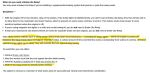
Does NOT work for 2021 and new F-150's. There is a lot of bad advice regarding this in the Q&A section that etrailer needs to update. Associates incorrectly have been including the Brake-Lite Relay kit in the list of items needed to tow late-model Ford trucks. However, with my 2023 F-150 XLT (push button start), it is simply impossible to install. The new Ford trucks do not even have a brake switch on the pedal and there is no visible wiring under the dash. I called Roadmaster, who immediately confirmed that they were aware of the issue. THE RELAY SWITCH IS NOT AN OPTION FOR 2021 AND NEWER F-150's. The only way to overcome the brake light override issue is to wait for the truck to enter "sleep mode." This occurs when you remove the key and don't open the door for 15 minutes. After that, the truck's electronics (body control module" shut off. Then the brake pedal can be pressed and the lights do not illuminate. Thus no relay is needed, you just have to wait 15 minutes. The motorhome wiring harness will work normally through the truck's tail lights, assuming you have installed the smart diode wiring kit for variable voltage. This part works great.

Roadmaster’s Brake-lite Relay Kit has worked flawlessly now for a year. A good friend of mine and I installed it on my ‘15 f150 FX 4 crew cab.
I’m quite pleased with Roadmaster and their products.
Clear instructions and an easy install. Worked great for keeping toad lights operating correctly with supplimental breaking system. Thanks for quick shipping!
Installed as directions said to and all things are working as they should be. Helpful installation guide and video from trailer
Keith C.

5/3/2025
It worked great until I sold the vehicle. Used eTrailer to set up my new vehicle
Not compatible with the 2022 Wrangler as the brake/turn signal is controlled by the BCM and there is no fuse for it on the fuse block.
Evidently Roadmaster had made some slight alterations from the depiction, for the better. The fuse wiring was a spade end with two fuse holders built in. The holder closest to the spades was for the original circuit and the other for the new circuit. This was very handy. I had watched the installation video and thought it would be fairly easy; therefore I attached the terminals to the green, black, and white wires before even going to the CR-V.
I did however purchase different spade connectors as I thought I may want to remove the brake relay switch in the future for another vehicle should I trade. Also the yellow connector is quite large and the video showed bending the wire over itself so that it would hold on the smaller wires. This was a wise decision.
What was the problem was the wiring in my CR-V. The video showed similar size wiring from the brake switch. What I found was smaller wire, loomed very close to the brake switch. Evidently Honda had made some modifications. I believe the wire was 22 gauge and there was no real way the blue or yellow connectors would have worked. That said, after disconnecting from the switch, stripping the loom back to get some exposed wiring, cutting and using the 22-16 gauge connectors, drilling a hole for the ground screw, etc. the switch worked perfectly.
I did vary the fuse location from the 7.5 Amp #29 Occupant Detection System (ODS) to the 15 Amp #28 Washer as I figured it would less likely interfere with any operation.
Richard
10/24/2018
Working great with no problems.
Self installed, and easy to do if you just follow the videos and read the instructions. Quality hardware and fully functional after a full year of use. Jeep JK
Michael
4/19/2025
After a year and many miles towing all lights and hardware are functioning like the day they were installed. Etrailer, keep supplying quality products and techs providing video installation steps.
Installed as part of the InvisiBrake system. Since the InvisiBrake works, the relay kit must be performing its function.
Easy install, works great in my ‘04 TJ Rubicon and with a Ready Brake Tow Bar. I never think about it- just hitch up, plug in and go.
Installing on 2020 Jeep Trailhawk :
Pic #0557 : Roadmaster Base Plate Kit , Demco Supplemental Braking System , Diode Wiring Kit , Demco Battery Charge Wire Kit
Pic # 0548 ,0551 , 0559 Had to adjust the bracket plate to line up with the upper bolt holes
Pic #6028 finished install , mounted the operating unit to the top fuse box cover using automotive Velcro . Air cylinder , controller and LED light installed . Aside from the base plate bracket not lining up with the upper bolt holes I would give it 4 stars . My son in law is a master at solving mechanical issues .
It did the job but could be easier if it was plug and play just a suggestion I would of paid extra for that
The video help was priceless…just watch and follow step by step instructions for easy installation! After a year of use it has performed flawlessly, very pleased.
I used this relay along with a separate switch to turn on Firestone air suspension compressor. Remember always use electric grease on connections. Thank you etrailer. God bless. Jesus saves.
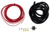
The “kit” is way over priced for what you get. The wire for the ignition connection is way too short to be useful. I could have bought all the parts at an auto store or Amazon for under $20.00.
Easy installation!
Pulled entire length of route 66 and then some. We had absolutely no issues with all of our etrailer equipment. Thanks for all of your help.
Need instruction on the vehicle that you ordered it for
Works as promised.
Simple, easy, effective. What else do you want.
Brake light has worked perfectly. No issues. Very reassuring for me as the driver to be able to see in the Motorhome's rearview camera when the F150 is braking.
Works great, easy to hook up and away we wenr
Great product but not required with the blue ox harness or the Hopkins harness
I ordered all the parts required to safely flat tow out 2017 Jeep Cherokee Trailhawk from etrailer.com. The only part they didn't have was the Mopar Flat Tow Enhancement kit Jeep requires to flat tow this model.
Ordering from them was great, the website is easy to use and I was able to locate all the pieces compatible with my specific vehicle. The expert recommendations help my decision choosing the right parts. I ordered from etrailer even though I found some of the parts on other websites a little cheaper. I chose to pay a little more because of all the effort etrailer has put into installation videos and guides. I was very pleasantly surprised to learn from etrailer that they have a price match guarantee!
So my equipment consisted of the following
Mopar Flat Tow Enhancement Kit (from Jeep)
Roadmaster Battery Charge Line Kit for Towed Vehicles
Mighty Cord 7-Way RV Style Trailer Connector - Trailer End
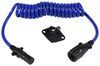
WesBarg 7-Way, RV-Style Connector w/ 6' Long Coiled Cable Trailer End
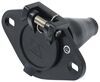
Pollak Black Plastic, 7-Pole, RV Blade-Style Trailer Socket - Vehicle End
Hopkins Custom Tail Light Wiring Kit for Towed Vehicles
SMI Stay-IN-Play DUO Supplemental Braking System
Roadmaster Brake-Lite Relay Kit for Towed Vehicles
Blue Ox Alpha Tow Bar - Motor Home Mount - 6,500 lbs
Blue Ox Base Plate Kit - Removable Arms
Blue Ox Tow Bar Cover - Aladdin, Aventa LX, Aventa II
The installation videos are great but not all inclusive. Take the time to read the instructions that come with the parts. This is a major project, I took about 30 hrs over a full week but as you'll see in the pictures I took s few extra steps to make a cleaner look.
Some of those extra steps:
The base plate install requires the bumper be modified cutting off a flange on each side, I spray painted this to prevent corrosion.
In the install video of the baseplate on the drivers side they use an extra quick link (not included) to run the safety cable around the wiper fluid reservoir. I took the time to remove it and run the safety cable behind it.
I didn't want our nice new vehicle to look like it can be towed so I played the brake away switch and 7 way trailer plug behind the license plate, so when not being towed our vehicle looks great!
Some things to be aware of. The Brake air cylinder that mounts to the brake pedal with four bolts may need longer bolts, it did on our Jeep. Spend the money for weather tight heat shrink crimp fittings. The Hopkins wire harness was about 1.5 feet short to get to my plug location. Buy extra zip ties, electrical tape and split loom.
I recommend reading all the various installation manuals and watching all the videos because the various components integrate together and if you install one at a time you'll be doing a bunch of extra work.
The brake light relay is a real pain in the butt, not because of the hardware but because of the location of the brake light switch which is very hard to get to.
Overall I am very happy with the products and how the installation looks. We haven't towed it yet but do not expect any problems.
Roy
7/30/2018
Still very happy with our purchase. We’ve towed over 10k miles and have had zero issues with our tow setup. I’ve shared my experience with several other RVrs and recommended your company for their needs. Thank you
Do you have a question about this Flat Tow Brake System?
Info for this part was:
At etrailer.com we provide the best information available about the products we sell. We take the quality of our information seriously so that you can get the right part the first time. Let us know if anything is missing or if you have any questions.


John
6/10/2025
Checking in after 1 year. No problems to report. Just works!